
Software Engineering
Introduction
Software Cost
The costs of software on a PC are often greater than the hardware cost.
More to maintain than it does to develop
Software engineering is concerned with cost-effective software development.
Software Project failure
- Increasing System Complexity.
- Failure to use software engineering methods.
Exp:
It is fairly easy to write computer programs without using software engineering methods and techniques.
Software products
Generic products
Sold to customer
Graphics programs, Project management tools; CAD software; Software for specific markets such as appointments systems for dentists
Customized products
Software that is commissioned by a specific customer to meet their own needs
Embedded control systems, Air traffic control software, Traffic monitoring systems
Essential attributes of good software
- Maintainability
- Dependability and Secutiry
- Efficiency
- Acceptability
All aspects of software production
Not just technical process of development. Also project management and the development of tools, methods etc. to support software production.
Importance of software engineering
More and more, individuals and society rely on advanced software systems.
It is usually cheaper, in the long run, to use software engineering methods and techniques of software systems rather than just write the programs as if it was a personal programming project.
Software process activities
- Software specification.
customers and engineers define the software that is to be produced and the constraints on its operation
- Software development.
where the software is designed and programmed
- Software validation.
where the software is checked to ensure that it is what the customer requires
- Software evolution.
where the software is modified to reflect changing customer and market requirements
General issues that affect software
Heterogeneity(不统一)
Different types of computer and mobile devices.
Business and social change
They changing pincredibly quickly as emerging economies develop and new technologies become abailabel.
Security and Trust
Software is intertwined with all aspects of our lives.
Scale
Be developed across a very wide range of scales, from very small
embedded systemsin portable or wearable devices through tointernet-scale,cloud-basesystems that serve a global community.
Application types
| Types | Descripe | Example |
|---|---|---|
| Stand-alone applications | Run on a local computer, inclued all necessary functionality and do not need to be connected to a network | Windows, Mac OS, Microsoft Word |
| Interactive transaction-based applications | Execute on a remote computer and are accessed by users from their own PCs or terminals. | web applications, e-commerce applications |
| Embedded control systems | control and manage hardware devices. | Medical Devices, Smartphones |
| Batch processing systems | Designed to process data in large batches, always business systems. They process large numbers of individual inputs to create corresponding outputs. | phone billing systems, salary payment systems. |
| Entertainment systems | Are primarily for personal use and which
are intended to entertain the user
(They can connect to the network) |
Games |
| Systems for modelling and simulation | Are developed by scientists and engineers to** model** physical processes or situations | Matlab |
| Data collection systems | Collect data from their environment using a set of sensors and send that data to other systems for processing. | wilderness weather station |
| Systems of systems | Are composed of a number of other software systems | School systems. Programming environments. |
Software engineering fundamentals
- Using a managed and understood development process.
- Dependability and performance are important for all types of system
- Understanding and managing the software specification and requirements are important
- Reuse software that has already been developed rather than write new software
Web-based software engineering
- Complex distributed systems
- Use the same fundamental ideas as other types of software system
- Software reuse is important
- Incremental and agile development
- Service-oriented systems (the software components are stand-alone web services)
- Rich interfaces
Software engineering ethics
- Involves wider responsibilities than simply the application of technical skills.
- Must behave in an honest and ethically responsible way if they are to be respected as professionals.
- Ethical behaviour is more than simply upholding the law but involves following a set of principles that are morally correct.
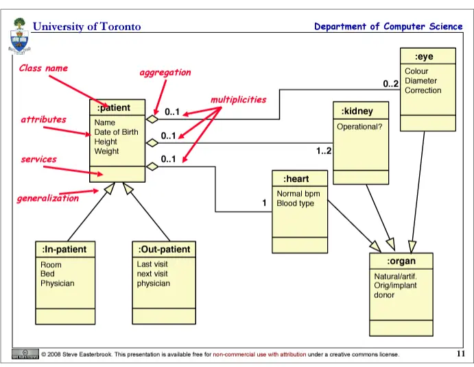
UML diagrams (Unified Modelling Language)
- Class Diagrams
information structure realtionships between data items
modular structure for the system
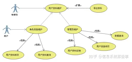
- Use Cases
user's view, lists functions, visual overview of the main requirements
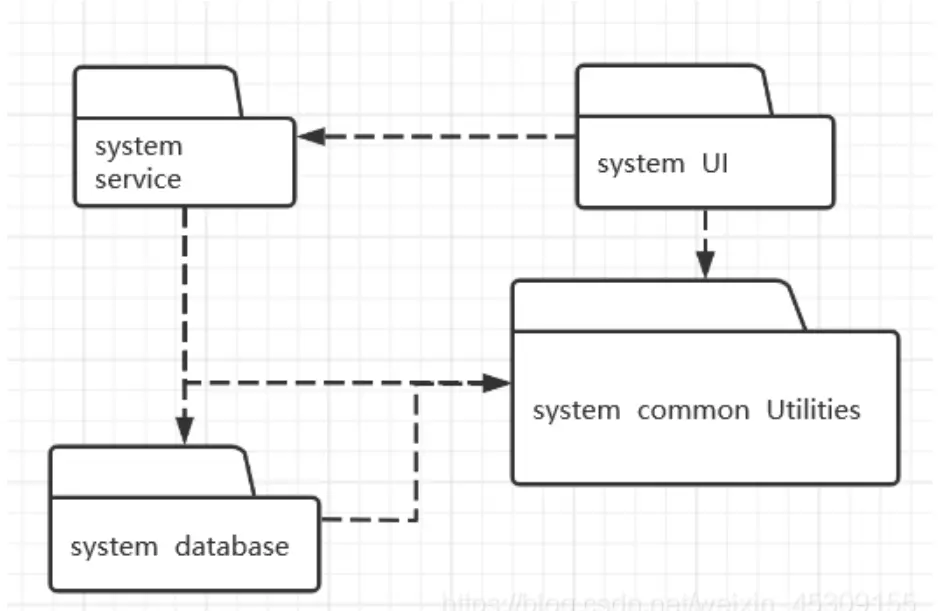
- UML Package Diagrams
Overall architecture, Dependencies between components
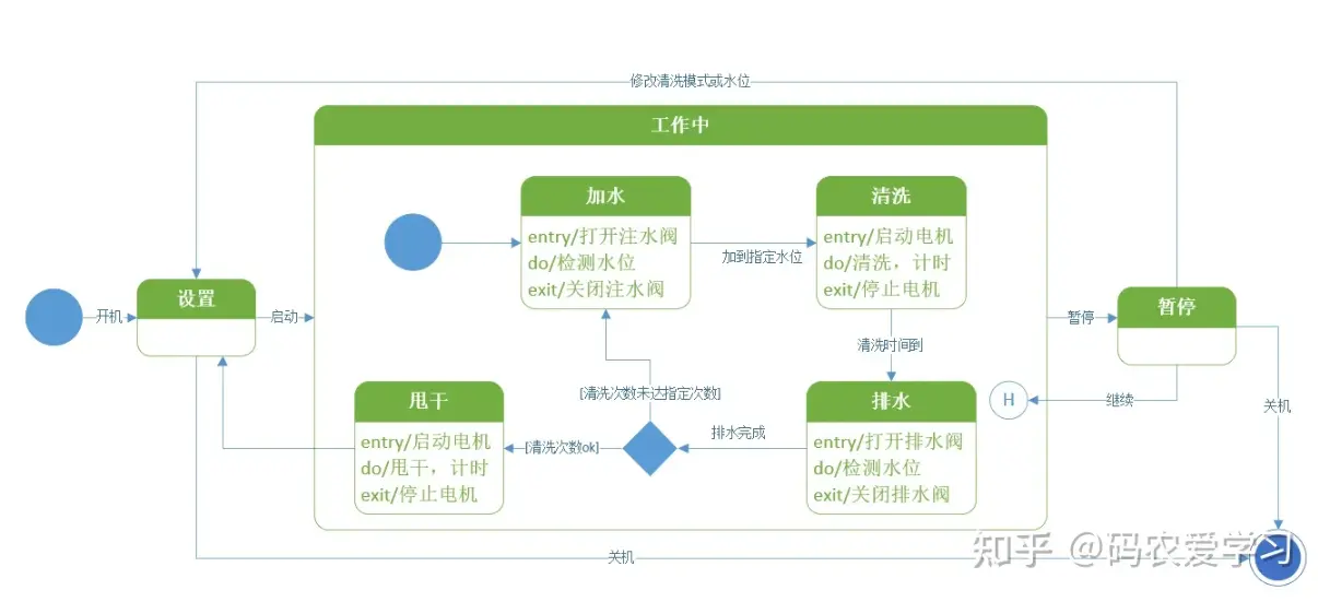
- Statecharts
responses to events, dynamic behavior, event ordering reachability, deadlock
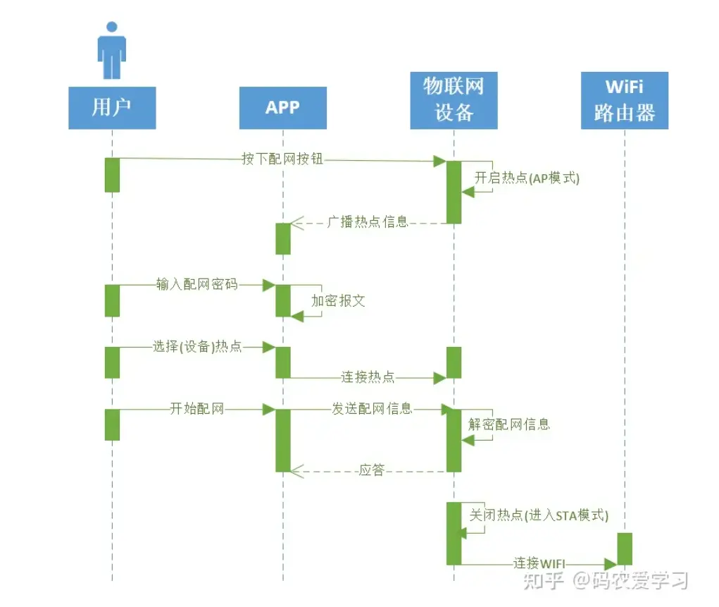
- UML Sequence Diagrams
individual scenario, interactions between users and system, Sqquence of messages
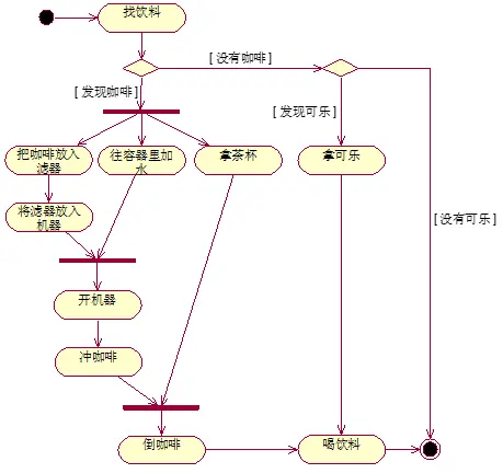
- Activaty Diagrams
Business process, concurrency and synchronization, dependencies betweens tasks
- Block Diagrams
Don't need details,
- Rectangle: Entity
- Rounded Rectangle: Action
- Round: Start
- Concentric circles: End
EXAMPLE:
Key points
- Software engineering is an engineering discipline that is concerned with all aspects of software production
- Essential software product attributes are maintainability, dependability and security, efficiency and acceptability.
- The high-level activities of specification, development, validation and evolution are part of all software processes.
- The fundamental notions of software engineering are universally applicable to all types of system development.
- There are many different types of system, and each requires appropriate software engineering tools and techniques for their development.(Each one is different)
- The fundamental ideas of software engineering are applicable to all types of software system
- Software engineers have responsibilities to the engineering profession and society. They should not simply be concerned with technical issues
- Professional societies publish codes of conduct which set out the standards of behaviour expected of their members.
Software Processes
Many different software processes but all involve:
- Specification – defining what the system should do;
- Design and implementation – defining the organization of the system
and implementing the system;
(development) - Validation – checking that it does what the customer wants;
(testing) - Evolution – changing the system in response to changing customer
needs.
(maintaines)
Total step
- specification
- user verbal/ writen requirement
- use case/ user story(UML diagram)
- decompose into entitle (quantitive attributes)
- key functionality
- refinement
Software process descriptions
Process descriptions may also include:
- Products, which are the outcomes of a process activity;
- Roles, which reflect the responsibilities of the people involved in the process;
- Pre- and post-conditions, which are statements that are true before and after a process activity has been enacted or a product produced.
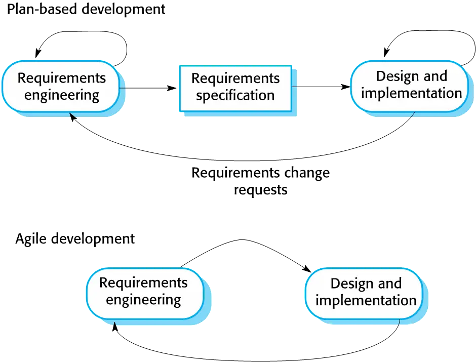
Plan-driven and agile processes
- Plan-driven processes are processes where all of the process activities are planned in advance and progress is measured against this plan.
- In agile processes, planning is incremental and it is easier to change the process to reflect changing customer requirements.
- In practice, most practical processes include elements of both plan-driven and agile approaches.
- There are no right or wrong software processes.
Software process models
- The waterfall model > Plan-driven model. Separate and distinct phases of specification and development.
- Incremental development > Specification, development and validation are interleaved. May be plan-driven or agile.
- Integration and configuration > The system is assembled from existing configurable components. May be plan-driven or agile.
- In practice, most large systems are developed using a process that incorporates elements from all of these models.
Waterfall model phases
There are separate identified phases in the waterfall model:
- Requirements analysis and definition
- System and software design
- Implementation and unit testing
- Integration and system testing
- Operation and maintenance
The main drawback of the waterfall model is the difficulty of accommodating change after the process is underway. In principle, a phase has to be complete before moving onto the next phase.
EXP: 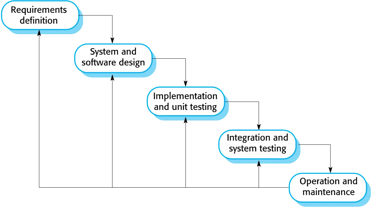
Problems
- Inflexible partitioning of the project into distinct stages makes it difficult to respond to changing customer requirements.
- Therefore, this model is only appropriate when the requirements are well-understood and changes will be fairly limited during the design process.
- Few business systems have stable requirements.
- The waterfall model is mostly used for large systems engineering projects where a system is developed at several sites.
- In those circumstances, the plan-driven nature of the waterfall model helps coordinate the work.
Incremental development
Incremental development is based on the idea of developing an initial implementation, exposing this to user comment and evolving it through several versions until an adequate system has been developed
EXP: 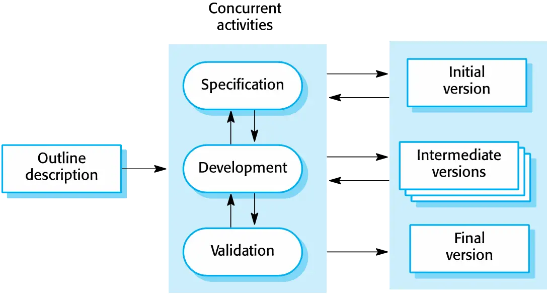
Incremental development benefits
- The cost of accommodating changing customer requirements is reduced. > The amount of analysis and documentation that has to be redone is much less than is required with the waterfall model.
- It is easier to get customer feedback on the development work that has been done. > Customers can comment on demonstrations of the software and see how much has been implemented.
- More rapid delivery and deployment of useful software to the customer is possible. > Customers are able to use and gain value from the software earlier than is possible with a waterfall process.
Incremental development problems
- The process is not visible. > Managers need regular deliverables to measure progress. If systems are developed quickly, it is not cost-effective to produce documents that reflect every version of the system.
- System structure tends to degrade
as new increments are added.
> Unless time and money is spent on refactoring to improve the software, regular change tends to corrupt its structure. Incorporating further software changes becomes increasingly difficult and costly.
Integration and configuration
- Based on software reuse where systems are integrated from existing components or application systems (sometimes called COTS -Commercial-off-the-shelf) systems).
- Reused elements may be configured to adapt their behaviour and functionality to a user’s requirements
- Reuse is now the standard approach for building many types of business system
Types of reusable software
- Stand-alone application systems (sometimes called COTS) that are configured for use in a particular environment.
- Collections of objects that are developed as a package to be integrated with a component framework such as .NET or J2EE.
- Web services that are developed according to service standards and which are available for remote invocation.
Reuse-oriented software engineering
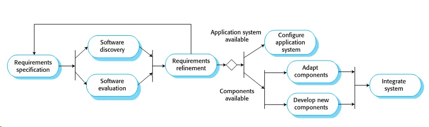 ### Key process stages
- Requirements specification
- Software discovery and evaluation
- Requirements refinement
- Application system configuration
- Component adaptation and integration
Advantages and disadvantages
- Reduced costs and risks as less software is developed from scratch
- Faster delivery and deployment of system
- But requirements compromises are inevitable so system may not meet real needs of users
- Loss of control over evolution of reused system elements
Process activities
- Real software processes are inter-leaved sequences of technical, collaborative and managerial activities with the overall goal of specifying, designing, implementing and testing a software system.
- The four basic process activities of specification, development, validation and evolution are organized differently in different development processes. > For example, in the waterfall model, they are organized in sequence, whereas in incremental development they are interleaved.
The requirements engineering process
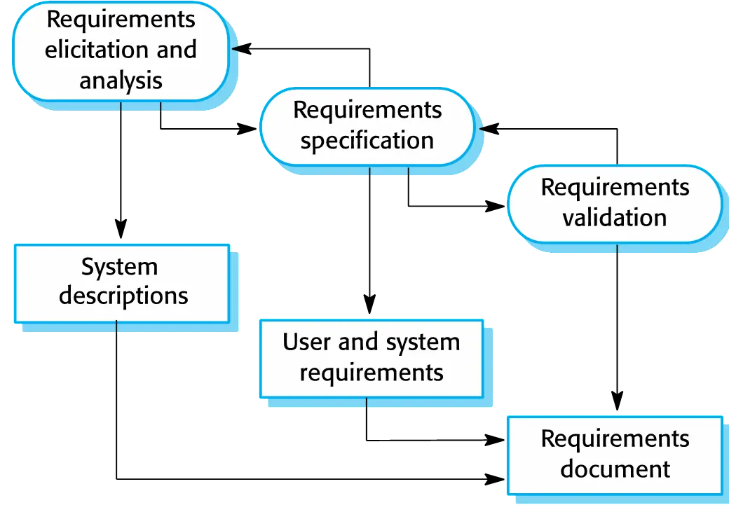
Software specification
- The process of establishing what services are required and the constraints on the system’s operation and development.
- Requirements engineering process
- Requirements elicitation and
analysis
- What do the system stakeholders require or expect from the system?
- Requirements specification
- Defining the requirements in detail
- Requirements validation
- Checking the validity of the requirements ### Software design and implementation
- Requirements elicitation and
analysis
- The process of converting the system specification into an executable system.
- Software design
- Design a software structure that realises the specification;
- Implementation
- Translate this structure into an executable program;
- The activities of design and implementation are closely related and may be inter-leaved.
A general model of the design process
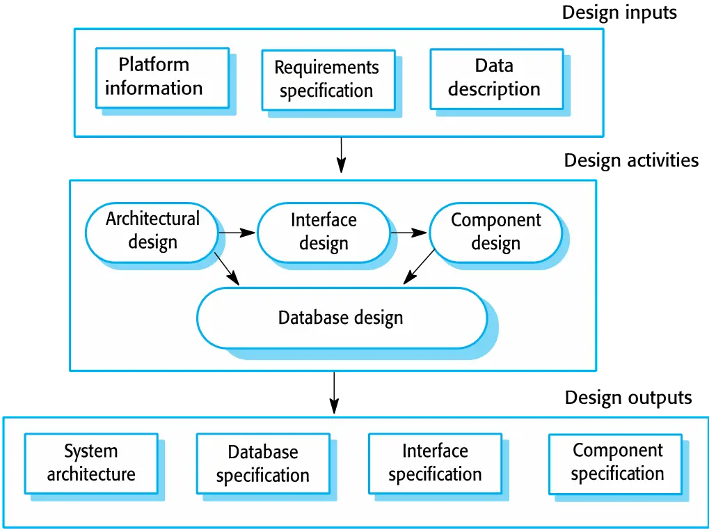
Design activities
- Architectural design, where you identify the overall structure of the system, the principal components (subsystems or modules), their relationships and how they are distributed.
- Database design, where you design the system data structures and how these are to be represented in a database.
- Interface design, where you define the interfaces between system components.
- Component selection and design, where you search for reusable components. If unavailable, you design how it will operate.
System implementation
- The software is implemented either by developing a program or programs or by configuring an application system.
- Design and implementation are interleaved activities for most types of software system.
- Programming is an individual activity with no standard process.
- Debugging is the activity of finding program faults and correcting these faults.
Software validation
- Verification and validation (V & V) is intended to show that a system conforms to its specification and meets the requirements of the system customer.
| Verification | Validation |
|---|---|
| Did we built products right( system conforms to its specification ) | Did we built a right product (system meets the requirements of the system customer) |
- Involves checking and review processes and system testing.
- System testing involves executing the system with test cases that are derived from the specification of the real data to be processed by the system.
- Testing is the most commonly used V & V activity.
Testing stages
- Component testing
- Individual components are tested independently;
- Components may be functions or objects or coherent groupings of these entities.
- System testing
- Testing of the system as a whole. Testing of emergent properties is particularly important.
- Customer testing
- Testing with customer data to check that the system
meets the customer’s needs. ### Testing phases in a
plan-driven software process (V-model)
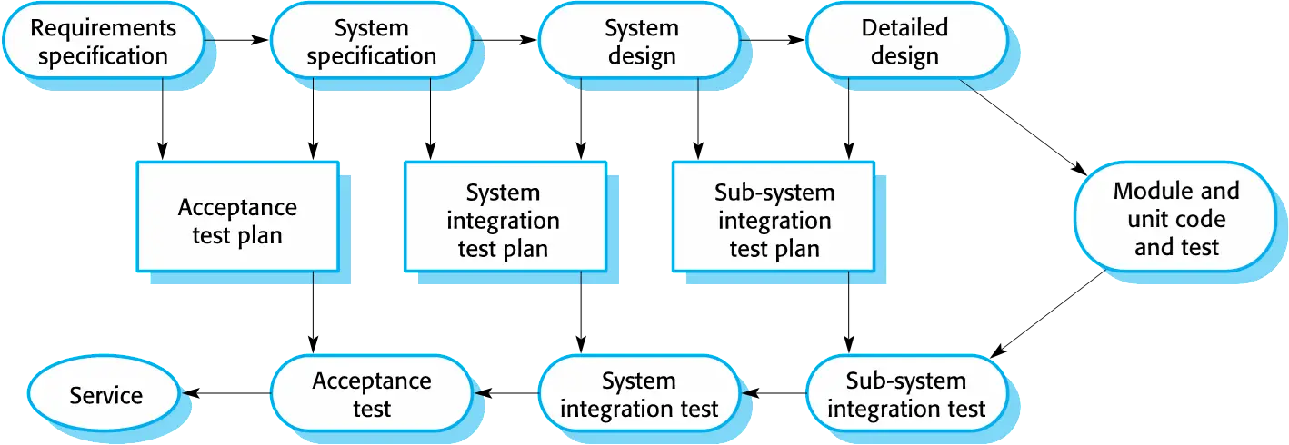
- Testing with customer data to check that the system
meets the customer’s needs. ### Testing phases in a
plan-driven software process (V-model)
Software evolution
Software is inherently flexible and can change.
As requirements change through changing business circumstances, the software that supports the business must also evolve and change.
Although there has been a demarcation between development and evolution (maintenance) this is increasingly irrelevant as fewer and fewer systems are completely new.
Coping with change
- System prototyping, where a version of the system or part of the system is developed quickly to check the customer’s requirements and the feasibility of design decisions. This approach supports change anticipation.
- Incremental delivery, where system increments are delivered to the customer for comment and experimentation. This supports both change avoidance and change tolerance.
Software prototyping
A prototype is an initial version of a system used to demonstrate concepts and try out design options. A prototype can be used in:
- The requirements engineering process to help with requirements elicitation and validation;
- In design processes to explore options and develop a UI design;
- In the testing process to run back-to-back tests.
Benefits of prototyping
- Improved system usability.
- A closer match to users’ real needs.
- Improved design quality.
- Improved maintainability.
- Reduced development effort.
The process of prototype development
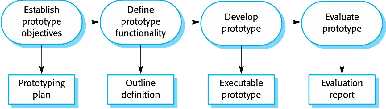
Prototype development
- May be based on rapid prototyping languages or tools
- May involve leaving out functionality
- Prototype should focus on areas of the product that are not well-understood;
- Error checking and recovery may not be included in the prototype;
- Focus on functional rather than non-functional requirements such as reliability and security
- Prototypes should be discarded after development as they are not a
good basis for a production system:
- It may be impossible to tune the system to meet non-functional requirements;
- Prototypes are normally undocumented;
- The prototype structure is usually degraded through rapid change;
- The prototype probably will not meet normal organisational quality standards.
Incremental delivery
- Rather than deliver the system as a single delivery, the development and delivery is broken down into increments with each increment delivering part of the required functionality.
- User requirements are prioritised and the highest priority requirements are included in early increments.
- Once the development of an increment is started, the requirements are frozen though requirements for later increments can continue to evolve.
Incremental development
- Develop the system in increments and evaluate each increment before proceeding to the development of the next increment;
- Normal approach used in agile methods;
- Evaluation done by user/customer proxy.
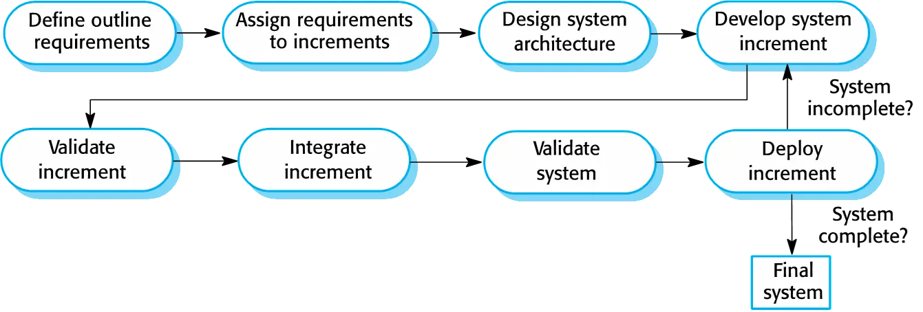
Incremental delivery
- Deploy an increment for use by end-users;
- More realistic evaluation about practical use of software;
- Difficult to implement for replacement systems as increments have less functionality than the system being replaced.
Adventages
- Customer value can be delivered with each increment so system functionality is available earlier.
- Early increments act as a prototype to help elicit requirements for later increments.
- Lower risk of overall project failure.
- The highest priority system services tend to receive the most testing.
problems
- Most systems require a set of basic facilities that are used by
different parts of the system.
- As requirements are not defined in detail until an increment is to be implemented, it can be hard to identify common facilities that are needed by all increments.
- The essence of iterative processes is that the specification is
developed in conjunction with the software.
- However, this conflicts with the procurement model of many organizations, where the complete system specification is part of the system development contract.
Process improvement
Approaches to improvement
- The process maturity approach, which focuses on improving process
and project management and introducing good software engineering
practice.
- The level of process maturity reflects the extent to which good technical and management practice has been adopted in organizational software development processes.
- The agile approach, which focuses on iterative development and the
reduction of overheads in the software process.
- The primary characteristics of agile methods are rapid delivery of functionality and responsiveness to changing customer requirements.
Key points
- Software processes are the activities involved in producing a software system. Software process models are abstract representations of these processes.
- General process models describe the organization of software processes.
- Examples of these general models include the ‘waterfall’ model, incremental development, and reuse-oriented development.
- Requirements engineering is the process of developing a software specification.
- Design and implementation processes are concerned with transforming a requirements specification into an executable software system.
- Software validation is the process of checking that the system conforms to its specification and that it meets the real needs of the users of the system.
- Software evolution takes place when you change existing software systems to meet new requirements. The software must evolve to remain useful.
- Processes should include activities such as prototyping and incremental delivery to cope with change.
- Processes may be structured for iterative development and delivery so that changes may be made without disrupting the system as a whole.
- The principal approaches to process improvement are agile approaches, geared to reducing process overheads, and maturity-based approaches based on better process management and the use of good software engineering practice.
Agile Software Development
Agile methods
Rapid software development
- Rapid development and delivery is important for software systems:
- BUsinesses operate in a fast-changing requirement and it is practically impossible to product a set of statble software requirements.
- Software has to evolve quickly to relfect changing business needs.
- Plan-driven software development is not agile.
- Plan-driven development not meet these business needs
- Agile development methods emerged in the late 1990s
Agile development
- Program specification ,desing and implementation are inter-leaved(相互交错)
- The system is developed as a series of versions or increments with stakeholders involved in version specification and evaluation
- Frequent delivery of new versions for evaluation
- Extensive tool support (e.g. automated testing tools) used to support development.
- Minimal documentation – focus on working code
Different between agile and plan-driven development
- Plan-Driven development
- Based around separate develpment stages with the outputs to be produced at each of these stages planned in advance.
- NOt necessarily waterfall model - plan-driven, incremental develpment is possible.
- Iteration occurs within activities.
- Agile development
- Specification, design, implementation and testing are inter-leaved and the outputs from the development process are decided through a process of negotiation during the software development process.
Agile methods
- Focus on the code rather than the design
- Are based on a iterative approach to software development
- Are intended to deliver Working software quickly and evolve this quickly to meet changing requirements.
- The aim is to reduce overheads in the software process and to be able to respond quickly to changing requirements without excessive rework.
Principle
| Princifple | Description |
|---|---|
| Customer Involvement | The customer is involved in the software development process.(Taks: provide an prioritize new system requirements and to evaluate the iterations of the system) |
| Incremental delivery | The software is delivered in incremental stages, with each stage being tested and accepted by the customer. |
| People not process | Team members should be left to develop their own ways of working without prescriptive process. |
| Embrace change | The software should be developed in a way that allows it to adapt to change. |
| Maintain simplicity | Focus on simplicity in both the software being developed and in the development process. |
Agile method applicability
Product development where a softwaer company is developing a small or medium-sized product for sale.
Agile development techniques
Extreme programming
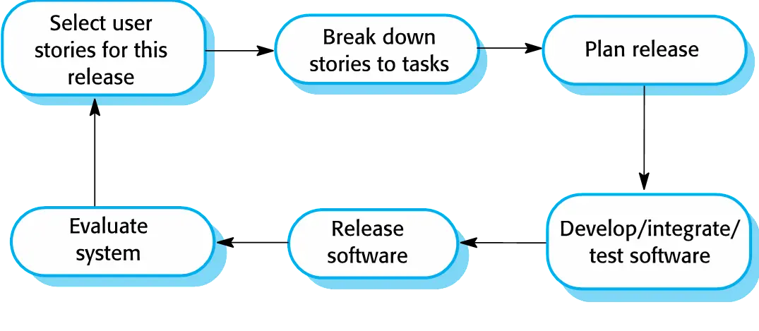
- Extreme Programming (XP) takes an ‘extreme’ approach to iterative
development.
- New versions may be built several times per day;
- Increments are delivered to customers every 2 weeks;
- All tests must be run for every build and the build is only accepted if tests run successfully.
- Extreme programmin release cycle
Principle
| Principle or practices | Description |
|---|---|
| Refactoring | To keep the code simple and maintainable. need to refactor the code continuously as soon as possible. |
| Collective ownership | The team members should be responsible for the code. Anyone can change anything. |
| Simple design | The design should be simple and easy to understand. |
| Continuous intergration | The code should be integrated to the latest version as soon as possible. All unit tests should be passed. |
| Sustainable pace | Large amounts of overtime are not considered as the net effect is often to reduce code quality and medium therm productivity. |
XP and agile principles
- Incremental development is supported through small, frequent system releases.
- Customer involvement means full-time customer engagement with the team.
- People not process through pair programming, collective ownership and a process that avoids long working hours.
- Change supported through regular system releases.
- Maintaining simplicity through constant refactoring of code.
Influential XP practices
- Extreme programming has a technical focus and is not easy to integrate with management practice in most organizations.
- Consequently, while agile development uses practices from XP, the method as originally defined is not widely used.
Key practices
- User stories for specification
- Refactoring
- Test-first development
- Pair programming
User stories for requirements
- In XP, a customer or user is part of the XP team and is responsible for making decisions on requirements.
- User requirements are expressed as user stories or scenarios.
- These are written on cards and the development team break them down into implementation tasks. These tasks are the basis of schedule and cost estimates.
- The customer chooses the stories for inclusion in the next release based on their priorities and the schedule estimates.
Refactoring
- It is worth spending time and effort anticipation changes as this reduces costs later inthe life cycle
- XP, however, maintains that this is not worthwhile as changes cannot be reliably anticipated. Rather, it proposes constant code improvement (refactoring) to make changes easier when they have to be implemented.
- Programming team look for possible software improvements and make these improvements even where there is no immediate need for them.
- This improves the understandability of the software and so reduces the need for documentation.
- Changes are easier to make because the code is well-structured and clear.
- However, some changes requires architecture refactoring and this is much more expensive
Test-first development
- Testing is central to XP and XP has developed an approach where the program is tested after every change has been made.
- XP testing features:
- Test-first development.
- Incremental test development from scenarios.
- User involvement in test development and validation.
- Automated test harnesses are used to run all component tests each time that a new release is built.
Test-driven development
- Writing tests before code clarifies the requirements to be implemented.
- Tests are written as programs rather than data so that they can be executed automaticallly. The test includes a check that it has executed correctly.
- All previous and new tests are run automatically when new functionality is added.
Customer involvement
- Help develop acceptance tests for the stories that are implemented in the next release of the system.
- Customer writes tests as development proceeds.
- Some they can not work ful-time.
Test automation
- tests are written as executable components before the task is implemented.
- As testing is automated, there is always a set of tests that can be quickly and easily executed
Problems with test-first development
- Programmers prefer programming to testing and sometimes they take short cuts when writing tests.
- Some tests can be very difficult to write incrementally.
- It difficult to judge the completeness of a set of tests.
Pair programming
- working in pairs, developing code together
- helps develop common ownership of code and spreads knowledge across the team
- It serves as an informal review process as each line of code is looked at by more than 1 person.
- It encourages refactoring as the whole team can benefit from improving the system code.
- The sharing of knowledge that happens during pair programming is very important as it reduces the overall risks to a project when team members leave.
- Pair programming is not necessarily inefficient and there is some evidence that suggests that a pair working together is more efficient than 2 programmers working separately.
Agile project management
- Stand approach to project management is plan-driven. Managers draw up a plan for the project showing what should be delivered, when it should be delivered and who will work on the development of the project deliverables.
- Agile project management requires a different approach, which is adapted to incremental development and the practices used in agile methods.
Scrum
- Scrum is a framework for managing projects. Focuses on managing iterative development rather than specific agile practices.
- There are three phases in Scrum.
- The initial phase is an outline planning phase where you establish
the general objectives for the project and design the software
architecture.
Specification and design - This is followed by a series of sprint cycles, where each cycle
develops an increment of the system.
Development and Validation - The project closure phase wraps up the project, completes required
documentation such as system help frames and user manuals and assesses
the lessons learned from the project.
Documentation
- The initial phase is an outline planning phase where you establish
the general objectives for the project and design the software
architecture.
Scrum terminology
- Product owner - An individual whose job is to identify product features or requirements, prioritize these for development and continuously review the product backlog to ensure that the project continues to meet critical business needs.
- Product backlog - This is a list of ‘to do’ items which the Scrum team must tackle.
- Development team - This is the group of people who are responsible for developing the product. no more than 7 people.
- Scrum Master - This is the person who helps and guides the team to achieve the goals of the project. (ScrumMaster should not be thought of as a project manager)
- Sprint - A development iteration. Usually 2-4 weeks long.
- Velocity - An estimate of how much product backlog effort that a team can cover in a single sprint. The number of story points completed in a sprint.
Product backlog - A list of ‘to do’ items which the Scrum team must tackle in the whole product.
Sprint backlog - A list of ‘to do’ items which the Scrum team must tackle in a sprint.
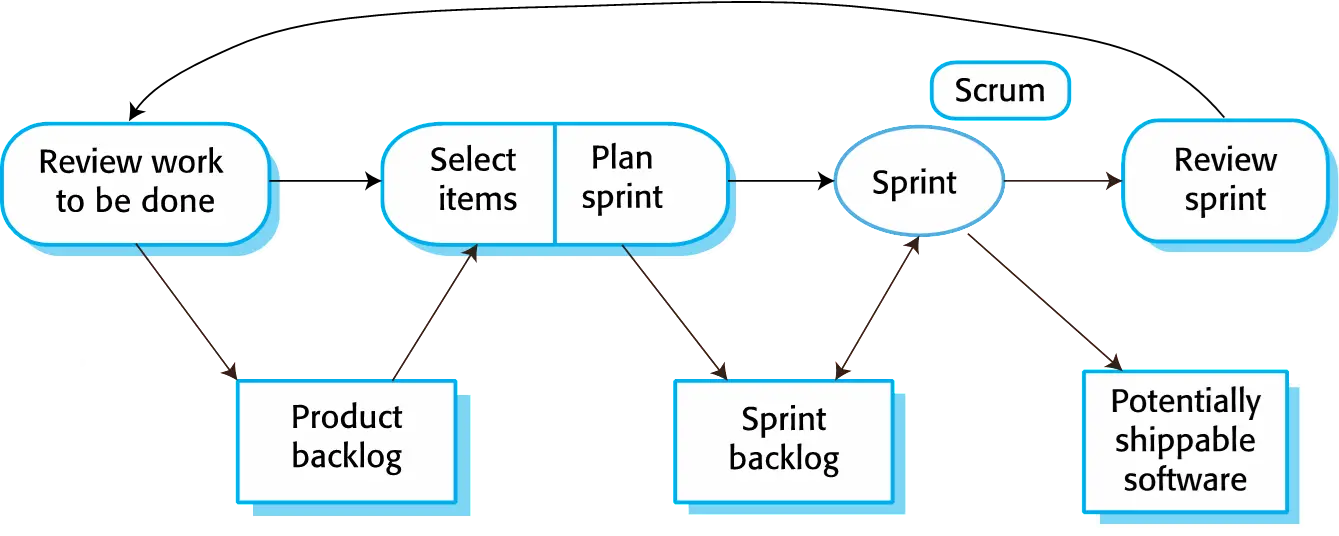
The starting point for planning is the product backlog, which is the list of work to be done on the project.
The selection phase involves all of the project team who work with the customer to select the features and functionality from the product backlog to be developed during the sprint.
Once these are agreed, the team organize themselves to develop the software.
During this stage the team is isolated from the customer and the organization, with all communications channelled through the so-called ‘Scrum master’.
The role of the Scrum master is to protect the development team from external distractions.
At the end of the sprint, the work done is reviewed and presented to stakeholders. The next sprint cycle then begins.
Teamwork in scrum
- The Scrum team is a self-organizing group that makes its own decisions and is responsible for its own work.
- The whole team attends short daily meetings (Scrums) where all team members share information, describe their progress since the last meeting, problems that have arisen and what is planned for the following day
Scrum benefits
- The product is broken down into a set of manageable and understandable chunks.
- Unstable requirements do not hold up progress.
- The whole team have visibility of everything and consequently team communication is improved.
- Customers see on-time delivery of increments and gain feedback on how the product works.
- Trust between customers and developers is established and a positive culture is created in which everyone expects the project to succeed.
Scaling agile methods
- Agile methods have proved to be successful for small and medium sized projects that can be developed by a small co-located team
Scaling out and scaling up
- Scaling up agile methods involves changing these to cope with larger, longer projects where there are multiple development teams, perhaps working in different locations.
- ‘Scaling up’ is concerned with using agile methods for developing
large software systems that cannot be developed by a
small team.
In one team - ‘Scaling out’ is concerned with how agile methods can be
introduced across a large organization with
many years of software development experience.
In many teams - When scaling agile methods it is important to maintain agile fundamentals: Flexible planning, frequent system releases, continuous integration, test-driven development and good team communications
Practical problems with agile methods
- The informality of agile development is incompatible with the legal approach to contract definition that is commonly used in large companies.
- Agile methods are most appropriate for new software development rather than software maintenance. Yet the majority of software costs in large companies come from maintaining their existing software systems.
- Agile methods are designed for small co-located teams yet much software development now involves worldwide distributed teams.
Agile methods and software maintenance
- Most organizations spend more on maintaining existing software than they do on new software development. So, if agile methods are to be successful, they have to support maintenance as well as original development.
- Two key issues:
- Are systems that are developed using an agile approach maintainable, given the emphasis in the development process of minimizing formal documentation?
- Can agile methods be used effectively for evolving a system in response to customer change requests?
- Problems may arise if original development team cannot be maintained.
Agile maintenance
- Key problems are:
- Lack of product documentation
- Keeping customers involved in the development process
- Maintaining the continuity of the development team
- Agile development relies on the development team knowing and understanding what has to be done.
- For long-lifetime systems, this is a real problem as the original developers will not always work on the system.
Agile and plan-driven methods
- Most projects include elements of plan-driven and agile processes.
Deciding on the balance depends on:
- Is it important to have a very detailed specification and design before moving to implementation? If so, you probably need to use a plan-driven approach.
- Is an incremental delivery strategy, where you deliver the software to customers and get rapid feedback from them, realistic? If so, consider using agile methods.
- How large is the system that is being developed? Agile methods are most effective when the system can be developed with a small co-located team who can communicate informally. This may not be possible for large systems that require larger development teams so a plan-driven approach may have to be used.
System issues
- How large is the system being developed?
- Agile methods are most effective a relatively small co-located team who can communicate informally.
- What type of system is being developed?
- Systems that require a lot of analysis
before implementation need a fairly detailed design to
carry out this analysis.
plan driven
- Systems that require a lot of analysis
before implementation need a fairly detailed design to
carry out this analysis.
- What is the expected system lifetime?
- Long-lifetime systems require documentation to
communicate the intentions of the system developers to the support team.
plan-driven
- Long-lifetime systems require documentation to
communicate the intentions of the system developers to the support team.
- Is the system subject to external regulation?
- If a system is regulated you will probably be required to produce detailed documentation as part of the system safety case.
People and teams
- How good are the designers and programmers in the development team?
- It is sometimes argued that agile methods require higher skill levels than plan-based approaches in which programmers simply translate a detailed design into code.
- How is the development team organized?
- Design documents may be required if the team is dsitributed.
- What support technologies are available?
- IDE support for visualisation and program analysis is essential if design documentation is not available.
Agile methods are difficult to apply to large systems
Scaling up to large systems
- A completely incremental approach to requirements engineering is impossible.
- There cannot be a single product owner or customer representative.
- For large systems development, it is not possible
to focus only on the code of the system.
- Cross-team communication mechanisms have to be designed and used.
- Continuous integration is practically impossible. However, it is essential to maintain frequent system builds and regular releases of the system.
Key points
- Agile methods are incremental development methods that focus on
rapid software development, frequent
releases of the software, reducing process
overheads by minimizing documentation
and producing high-quality code.
- Agile development practices include
- User stories for system specification
- Frequent releases of the software,
- Continuous software improvement
- Test-first development
- Customer participation in the development team.
- Scrum is an agile method that provides a
project management framework.
- It is centred round a set of sprints, which are fixed time periods when a system increment is developed.
- Many practical development methods are a mixture of plan-based and agile development.
- Scaling agile methods for large systems is
difficult.
- Large systems need up-front design and some documentation and organizational practice may conflict with the informality of agile approaches.
Requirements Engineering

- The process of establishing the services that a customer requires from a system and the constraints under which it operates and is developed.
- The system requirements are the descriptions of the system services and constraints that are generated during the requirements engineering process.
What is a requirement
- It may range from a high-level abstract statement of a service or of a system constraint to a detailed mathematical functional specification.
- This is inevitable as requirements may serve a dual function
- May be the basis for a bid for a contract - therefore must be open to interpretation;
- May be the basis for the contract itself - therefore must be defined in detail;
- Both these statements may be called requirements.
Types of requirement
- User requirements
- Statements in natural language plus diagrams of the services the system provides and its operational constraints. Written for customers.
- System requirements
- A structured document setting out detailed descriptions of the system’s functions, services and operational constraints. Defines what should be implemented so may be part of a contract between client and contractor.
System stakeholders
- Any person or organization who is affected by the system in some way and so who has a legitimate interest
- Stakeholder types
- End users
- System managers
- System owners
- External stakeholders
Stakeholders in the Mentcare system
- Patients whose information is recorded in the system.
- Doctors who are responsible for assessing and treating patients.
- Nurses who coordinate the consultations with doctors and administer some treatments.
- Medical receptionists who manage patients’ appointments.
- IT staff who are responsible for installing and maintaining the system.
- A medical ethics manager who must ensure that the system meets current ethical guidelines for patient care.
- Health care managers who obtain management information from the system.
- Medical records staff who are responsible for ensuring that system information can be maintained and preserved, and that record keeping procedures have been properly implemented.
Agile methods and requirements
- Many agile methods argue that producing detailed system requirements is a waste of time as requirements change so quickly.
- The requirements document is therefore always out of date.
- Agile methods usually use incremental requirements engineering and may express requirements as ‘user stories’
- This is practical for business systems but problematic for systems that require pre-delivery analysis
Functional and non-functional requirements
- Functional requirements
- Statements of services the system should provide, how the system should react to particular inputs and how the system should behave in particular situations.
- May state what the system should not do.
- Non-functional requirements
- Constraints on the services or functions offered by the system such as timing constraints, constraints on the development process, standards, etc.
- Often apply to the system as a whole rather than individual features or services.
- Domain requirements
- Constraints on the system from the domain of operation
Functional requirements
- Describe functionality or system services.
- Depend on the type of software, expected users and the type of system where the software is used.
- Functional user requirements may be high-level statements of what the system should do.
- Functional system requirements should describe the system services in detail.
Requirements imprecision
- Problems arise when functional requirements are not precisely stated.
- Ambiguous requirements may be interpreted in different ways by developers and users.
- Consider the term ‘search’ in requirement 1
- User intention – search for a patient name across all appointments in all clinics;
- Developer interpretation – search for a patient name in an individual clinic. User chooses clinic then search.
Requirements completeness and consistency
- In principle, requirements should be both complete and consistent.
- Complete
- They should include descriptions of all facilities required.
- Consistent
- There should be no conflicts or contradictions in the descriptions of the system facilities.
- In practice, because of system and environmental complexity, it is impossible to produce a complete and consistent requirements document.
Non-functional requirements
- These define system properties and
constraints e.g. reliability, response
time and storage requirements. Constraints are
I/O device capability, system representations, etc.
throughput - Process requirements may also be specified mandating a particular IDE, programming language or development method.
- Non-functional requirements may be more critical
than functional requirements. If these are not met, the system
may be useless.
avaliability reliability
Non-functional requirements implementation
- Non-functional requirements may affect the overall
architecture of a system rather than the individual components.
- For example, to ensure that performance requirements are met, you may have to organize the system to minimize communications between components.
- A single non-functional requirement, such as a security requirement,
may generate a number of related functional
requirements that define system services that are required.
- It may also generate requirements that restrict existing requirements.
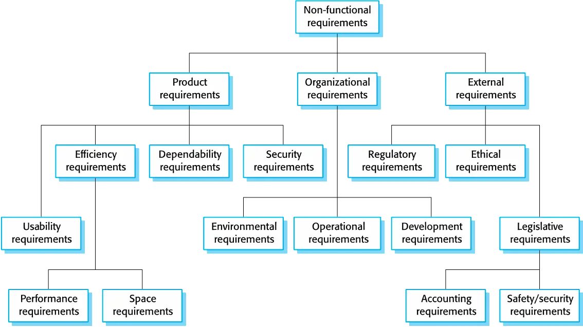
Non-functional classifications
- Product requirements
- Requirements which specify that the delivered product must behave in a particular way e.g. execution speed, reliability, etc.
- Organisational requirements
- Requirements which are a consequence of organisational policies and procedures e.g. process standards used, implementation requirements, etc.
- External requirements
- Requirements which arise from factors which are external to the system and its development process e.g. interoperability requirements, legislative requirements, etc.
Goals and requirements
- Non-functional requirements may be very difficult to state precisely and imprecise requirements may be difficult to verify.
- Goal
- A general intention of the user such as ease of use.
- Verifiable non-functional requirement
- A statement using some measure that can be objectively tested.
- Goals are helpful to developers as they convey the intentions of the system users.
Usability requirements(EXP.)
- The system should be easy to use by medical staff and should be organized in such a way that user errors are minimized. (Goal)
- Medical staff shall be able to use all the system functions after four hours of training. After this training, the average number of errors made by experienced users shall not exceed two per hour of system use. (Testable non-functional requirement)
Metrics for specifying nonfunctional requirements
| Property | Measure |
|---|---|
| Speed | Processed transactions/second \ User/event response time \ Screen refresh time |
| Size | Mbytes \ Number of ROM chips |
| Ease of use | Training time \ Number of help frames |
| Reliability | Mean time to failure \ Probability of unavailability \ Rate of failure occurrence \ Availability |
| Robustness | Time to restart after failure \ Percentage of events causing failure \ Probability of data corruption on failure |
| Portability | Percentage of target dependent statements \ Number of target systems |
Requirements Engineering Processes
- Common processes
- Requirements elicitation (需求引出)
- Requirements analysis
- Requirements validation
- Requirements management. ### Requirements elicitation and analysis
- Sometimes called requirements elicitation or requirements discovery
- Involves techinical staff working with customers to find out about the application domain, the services that the system should provide and the system's operational constraints.
- May involve end-users, managers, engineers involved in maintenance domain experts, trade unions, etc. These are called stakeholders.
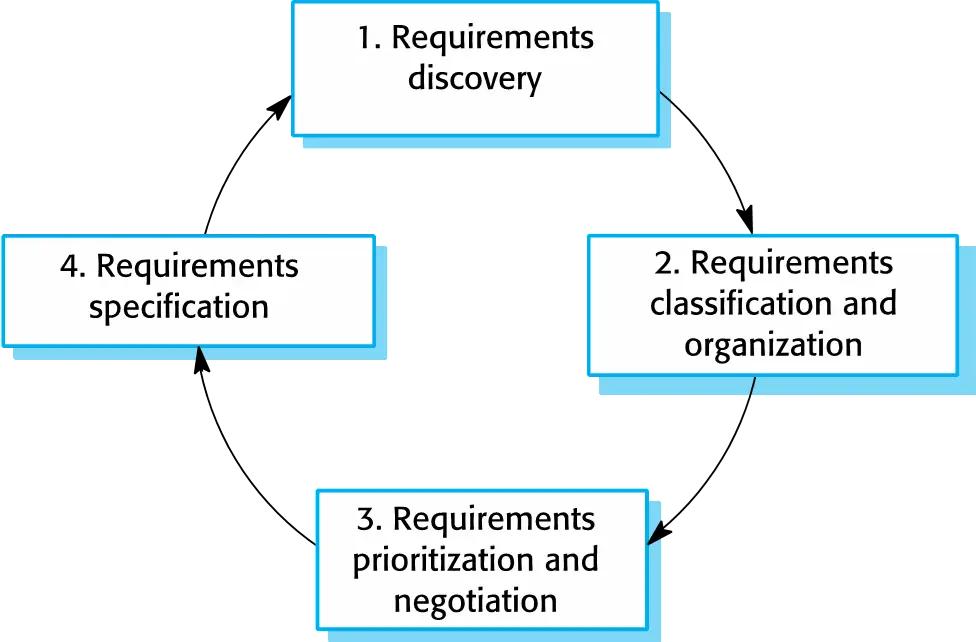
Requirements elicitation
Stages
- Requirements discovery
- Interacting with stakeholders to discover their requirements. Domain requirements are also discovered at theis stage
- Requirements classification and organization.
- Groups related requirements and organises them into coherent clusters.
- Requirements prioritization and negotiation
- Prioritising requirements and resolving requirements conflicts.
- Requirements specification
- Requirements are documented and input into the next round of the spiral.
Problem
- Stakeholders don’t know what they really want.
- Stakeholders express requirements in their own terms.
- Different stakeholders may have conflicting requirements.
- Organisational and political factors may influence the system requirements.
- The requirements change during the analysis process. New stakeholders may emerge and the business environment may change.
Interviewing
Types
- Closed interviews based on pre-determined list of questions
- Open interviews where various issues are explored with stakeholders.
Effective interviewing
- Be open-minded, avoid pre-conceived ideas about the requirements and are willing to listen to stakeholders.
- Prompt the interviewee to get discussions going using a springboard question, a requirements proposal, or by working together on a prototype system.
Interviews in practice
- Normally a mix of closed and open-ended interviewing.
- Interviews are good for getting an overall understanding of what stakeholders do and how they might interact with the system.
- Interviewers need to be open-minded without pre-conceived(先入为主) ideas of what the system should do
- You need to prompt the use to talk about the system by suggesting requirements rather than simply asking them what they want.
Problems
- Application specialists may use language to describe their work that isn’t easy for the requirements engineer to understand.
- Interviews are not good for understanding domain
requirements
- Requirements engineers cannot understand specific domain terminology;
- Some domain knowledge is so familiar that people find it hard to articulate or think that it isn’t worth articulating.
Stories and scenarios
- Scenarios and user stories are reql-life examples of how a system can be used.
- Stories and scenarios are a description of how a system may be used for a particular task.
- Because they are based on a practical situation, stakeholders can relate to them and can comment on their situation with respect to the story.
Scenarios
- A structured form of user story
- Scenarios should include
- A description of the starting situation;
- A description of the normal flow of events;
- A description of what can go wrong;
- Information about other concurrent activities;
- A description of the state when the scenario finishes.
Requirements specification
- It is the process of writing down the user and system requirements in a requirements document
- User requirements have to be understandable by end-users and customers who do not have a technical background.
- System requirements are more detailed requirements and may include more technical information.
- The requirements may be part of a contract for the
system development
- It is therefore important that these are as complete as possible
Ways of writing a system requirements specification
- Natural language: The requirements are written using numbered sentences in natural language. Each sentence should express one requirement.
- Structured natural language: Are written in natural language on a standard form or template. Each field provides information about an aspect of the requirement.
- Design description language: Uses a language like a programming language, but with more abstract features to specify the requirements by defining an operational model of the system.
- Graphical notations: UML use case and sequence diagrams are commonly used.
- Mathematical specifications: Base on mathematical concepts.
Requirements and design
- In principle, requirements should state what the system should do and the design should describe how it does this.
- In practice, requirements and design are inseparable
- A system architecture may be designed to structure the requirements;
- The system may inter-operate with other systems that generate design requirements;
- The use of a specific architecture to satisfy non-functional requirements may be a domain requirement.
- This may be the consequence of a regulatory requirement.
Guidelines for writing requirement
- Invent a standard format and use it for all requirements.
- Use language in a consistent way. Use shall for mandatory requirements, should for desirable requirements.
- Use text highlighting to identify key parts of the requirement.
- Avoid the use of computer jargon.
- Include an explanation (rationale) of why a requirement is necessary.
Structured specifications
- An approach to writing requirements where the freedom of the requirements writer is limited and requirements are written in a standard way.
- This works well for some types of requirements e.g. requirements for embedded control system but is sometimes too rigid for writing business system requirements.
Form-based specifications
- Definition of the function or entity.
- Description of inputs and where they come from.
- Description of outputs and where they go to.
- Information about the information needed for the computation and other entities used.
- Description of the action to be taken.
- Pre and post conditions (if appropriate).
- The side effects (if any) of the function.
Tabular specification
- Used to supplement natural language.
- Particularly useful when you have to define a number of possible alternative courses of action.
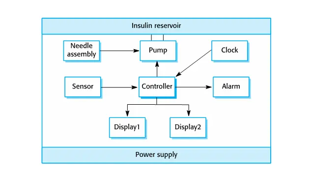
- For example, the insulin pump systems bases its computations on the rate of change of blood sugar level and the tabular specification explains how to calculate the insulin requirement for different scenarios.
Requirements validation
- Concerned with demonstrating that the requirements define the system that the customer really wants.
- Requirements error costs are high so validation is
very important
- Fixing a requirements error after delivery may cost up to 100 times the cost of fixing an implementation error.
Requirements checking
- Validity: Does the system provide the functions which best support the customer’s needs?
- Consistency: Are there any requirements conflicts?
- Completeness: Are all functions required by the customer included?
- Realism: Can the requirements be implemented given available budget and technology
- Verifiability: Can the requirements be checked?
Validation techniques
- Requirements reviews
- Systematic manual analysis of the requirements
- Prototyping
- Using an executable model of the system to check requirements.
- Test-case generation
- Developing tests for requirements to check testability.
Requirements reviews
- Regular reviws should be held while the requirements definition is being formulated.
- Both client and contractor staff should be involved in reviews.
- Reviews may be formal (with completed documents) or informal. Good communications between developers, customers and users can resolve problems at an early stage.
Review checks
- Verifiability
- Is the requirement realistically testable?
- Comprehensibility
- Is the requirement properly understood?
- Traceability
- Is the origin of the requirement clearly stated?
- Adaptability
- Can the requirement be changed without a large impact on other requirements?
Requirements Change
Reason:
- The business and technical environment of the system always changes after installation
- The people who pay for a system and the users of that system are rarely the same people.
- Large systems usually have a diverse user community with many users having different requirements and priorities that may be conflicting or contradictory
Requirements management
- Requirements management is the process of managing changing requirements during the requirements engineering process and system development.
- New requirements emerge as a system is being developed and after it has gone into use.
- You need to keep track of individual requirements and maintain links between dependent requirements so that you can assess the impact of requirements changes. You need to establish a formal process for making change proposals and linking these to system requirements.

Key points
- Requirements for a software system set out what the system should do and define constraints on its operation and implementation.
- Functional requirements are statements of the services that the system must provide or are descriptions of how some computations must be carried out.
- Non-functional requirements often constrain the system being developed and the development process being used.
- They often relate to the emergent properties of the system and therefore apply to the system as a whole.
- The requirements engineering process is an iterative process that includes requirements elicitation, specification and validation.
- Requirements elicitation is an iterative process that can be represented as a spiral of activities – requirements discovery, requirements classification and organization, requirements negotiation and requirements documentation.
- You can use a range of techniques for requirements elicitation including interviews and ethnography. User stories and scenarios may be used to facilitate discussions.
- Requirements specification is the process of formally documenting the user and system requirements and creating a software requirements document.
- The software requirements document is an agreed statement of the system requirements. It should be organized so that both system customers and software developers can use it.
- Requirements validation is the process of checking the requirements for validity, consistency, completeness, realism and verifiability.
- Business, organizational and technical changes inevitably lead to changes to the requirements for a software system. Requirements management is the process of managing and controlling these changes.
System Modeling
- System modeling is the process of describing a system in a formal way.
- It use on many steps of software development process.( Specification, System design, After increatmentation)
- Using some kind of graphical notation, such as UML diagram
- Helps the analyst to understand the functionalitu of the system and models are used to communicate with customers.
Existing and planned system models
+ Models of the existing system are used during
requirements engineering. + Models of the new system
are used during requirements engineering to help explain the proposed
requirements to other system stakeholders. + In a model-driven
engineering process, it is possible to generate a complete or partial
system implementation from the system model.
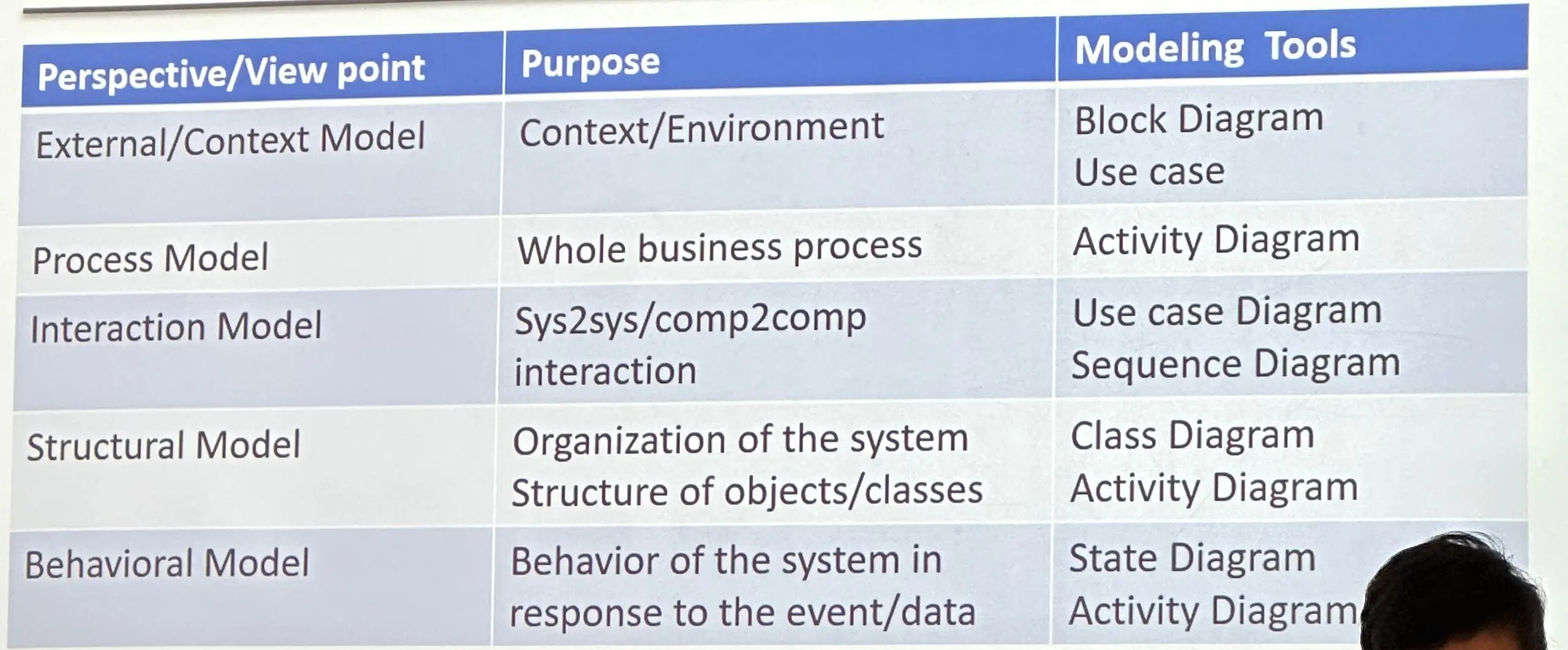
System perspectives
+ An external perspective, where you
model the context or
environment of the system.
context modeling + An interaction
perspective, where you model the interactions
between a system and its environment, or between the components of a
system. interaction modeling + A structural
perspective, where you model the organization
of a system or the structure of the
data that is processed by the system.
Structural modeling + A behavioral
perspective, where you model the dynamic behavior of the system
and how it responds to events. behavioral modeling
Context models
- Are used to illustrate the operational context of a system - they show what lies outside the system boundaries.
- Social and organisational concerns may affect the decision on where to position system boundaries.
- Architectural models show the system and its relationship with other systems.
- ALways use use case diagram and block diagram. ### System boundaries
- Are established to define what is inside and what is outside the system
- The position of the system boundary has a profound effect on the system requirements.
- Defining a system boundary is a political judgment.
Process perspective (Process Modeling)
- Context models simply show the other systems in the environment, not how the system being developed is used in that environment.
- Process models reveal how the system being developed is used in broader business process
- UML activity diagrams may be used to define business process models.
Iteraction models
- Modeling user interaction is important as it helps to identify user requirements.
- Modeling system-to-system interaction highlights the communication problems that may arise.
- Modeling component interaction helps us understand if a proposed system structure is likely to deliver the required system performance and dependability.
Use case diagramsandsequence diagramsmay be used for interaction modeling.
Structural models
- Structural models of software display the organization of a system in terms of the components that make up that system and their relationships.
- Structural models may be static models, which show the structure of the system design, or dynamic models, which show the organization of the system when it is executing.
- You create structural models of a system when you are discussing and designing the system architecture.
- Always use
Class DiagramandActivity Diagram.
Generalization(inheritance)
- Generalization is an everyday technique that we use to manage complexity.
- Rather than learn the detailed characteristics of every entity that we experience, we place these entities in more general classes (animals, cars, houses, etc.) and learn the characteristics of these classes.
- This allows us to infer that different members of these classes have some common characteristics e.g. squirrels and rats are rodents.
- In modeling systems, it is often useful to examine the classes in a system to see if there is scope for generalization. If changes are proposed, then you do not have to look at all classes in the system to see if they are affected by the change.
- In object-oriented languages, such as Java, generalization is implemented using the class inheritance mechanisms built into the language.
- In a generalization, the attributes and operations associated with higher-level classes are also associated with the lower-level classes.
- The lower-level classes are subclasses inherit the attributes and operations from their superclasses. These lower-level classes then add more specific attributes and operations.
Behavioral models
- Behavioral models are models of the dynamic behavior of a system as it is executing. They show what happens or what is supposed to happen when a system responds to a stimulus from its environment.
- You can think of these stimuli as being of two types:
DataSome data arrives that has to be processed by the system.(activity diagramandsequence diagram)EventsSome event happens that triggers system processing. Events may have associated data, although this is not always the case.(State diagram)
Data-driven modeling
- Many business systems are data-processing systems that are primarily driven by data. They are controlled by the data input to the system, with relatively little external event processing.
- Data-driven models show the sequence of actions involved in processing input data and generating an associated output.
- They are particularly useful during the analysis of requirements as they can be used to show end-to-end processing in a system.
Event-driven modeling
- Real-time systems are often event-driven, with minimal data processing. For example, a landline phone switching system responds to events such as ‘receiver off hook’ by generating a dial tone.
- Event-driven modeling shows how a system responds to external and internal events.
- It is based on the assumption that a system has a finite number of states and that events (stimuli) may cause a transition from one state to another.
State machine models
- These model the behaviour of the system in response to external and internal events.
- They show the system’s responses to stimuli so are often used for modelling real-time systems.
- State machine models show system states as nodes and events as arcs between these nodes. When an event occurs, the system moves from one state to another.
- Statecharts are an integral part of the UML and are used to represent state machine models.
Key poins
- A model is an abstract view of a system that ignores system details. Complementary system models can be developed to show the system’s context, interactions, structure and behaviour.
- Context models show how a system that is being modeled is positioned in an environment with other systems and processes.
- Use case diagrams and sequence diagrams are used to describe the interactions between users and systems in the system being designed. Use cases describe interactions between a system and external actors; sequence diagrams add more information to these by showing interactions between system objects.
- Structural models show the organization and architecture of a system. Class diagrams are used to define the static structure of classes in a system and their associations.
- Behavioral models are used to describe the dynamic behavior of an executing system. This behavior can be modeled from the perspective of the data processed by the system, or by the events that stimulate responses from a system.
- Activity diagrams may be used to model the processing of data, where each activity represents one process step.
- State diagrams are used to model a system’s behavior in response to internal or external events.
Architectural Design
- Architectural design is concerned with understanding how a software system should be organized and designing the overall structure of that system.
- Architectural design is the critical link between design and requirements engineering, as it identifies the main structural components in a system and the relationships between them.
- The output of the architectural design process is an architectural model that describes how the system is organized as a set of communicating components.
Agility and architecture
- It is generally accepted that an early stage of agile processes is to design an overall systems architecture.
- Refactoring the system architecture is usually expensive because it affects so many components in the system
Architectural abstraction
- Architecture in the small is concerned with the
architecture of individual programs. At this level, we
are concerned with the way that an individual program is decomposed into
components.
- Architecture in the large is concerned with the architecture of complex enterprise systems that include other systems, programs, and program components. These enterprise systems are distributed over different computers, which may be owned and managed by different companies.
Advantages of explicit architecture
- Stakeholder communication
- Architecture may be used as a focus of discussion by system stakeholders.
- System analysis
- Means that analysis of whether the system can meet its non-functional requirements is possible. Large-scale reuse The architecture may be reusable across a range of systems Product-line architectures may be developed.
Use of architectural models
- As a way of facilitating discussion about the
system design
- A high-level architectural view of a system is useful for communication with system stakeholders and project planning because it is not cluttered with detail. Stakeholders can relate to it and understand an abstract view of the system. They can then discuss the system as a whole without being confused by detail.
- As a way of documenting an architecture that has
been designed
- The aim here is to produce a complete system model that shows the different components in a system, their interfaces and their connections.
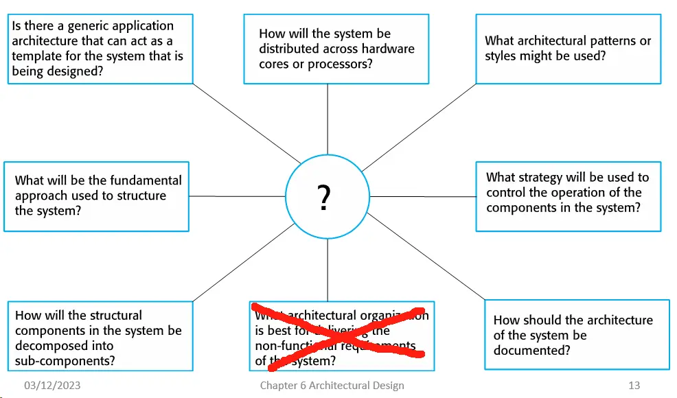
Architectural design decisions
- Architectural design is a creative process, so the process differs depending on the type of system being developed.
- However, a number of common decisions span all design processes and these decisions affect the non-functional characteristics of the system.
Architecture reuse
- Systems in the same domain often have similar architectures that reflect domain concepts.
- Application product lines are built around a core architecture with variants that satisfy particular customer requirements.
- The architecture of a system may be designed around one of
more architectural patterns or ‘styles’.
- These capture the essence of an architecture and can be instantiated in different ways.
Architecture and system characteristics
- Performance
- Localize critical operations and minimize communications. Use large rather than fine-grain components.
- Security
- Use a layered architecture with critical assets in the inner layers.
- Safety
- Localize safety-critical features in a small number of sub-systems.
- Availability
- Include redundant components and mechanisms for fault tolerance.
- Maintainability
- Use fine-grain, replaceable components.
- Scalability
- Meansure the maximum users
Architectural views
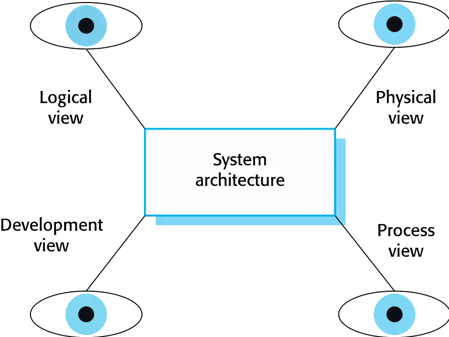
4 + 1 view model of software architecture
- A logical view, which shows the key abstractions in the system as objects or object classes.
- A process view, which shows how, at run-time, the system is composed of interacting processes.
- A development view, which shows how the software is decomposed for development.
- A physical view, which shows the system hardware and how software components are distributed across the processors in the system.
- Related using use cases or scenarios (+1)
Representing architectural views
- Some people argue that the Unified Modeling Language (UML) is an appropriate notation for describing and documenting system architectures
- I disagree with this as I do not think that the UML includes abstractions appropriate for high-level system description.
- Architectural description languages (ADLs) have been developed but are not widely used
Architectural patterns
- Patterns are a means of representing, sharing and reusing knowledge.
- An architectural pattern is a stylized description of good design practice, which has been tried and tested in different environments.
- Patterns should include information about when they are and when the are not useful.
- Patterns may be represented using tabular and graphical descriptions.
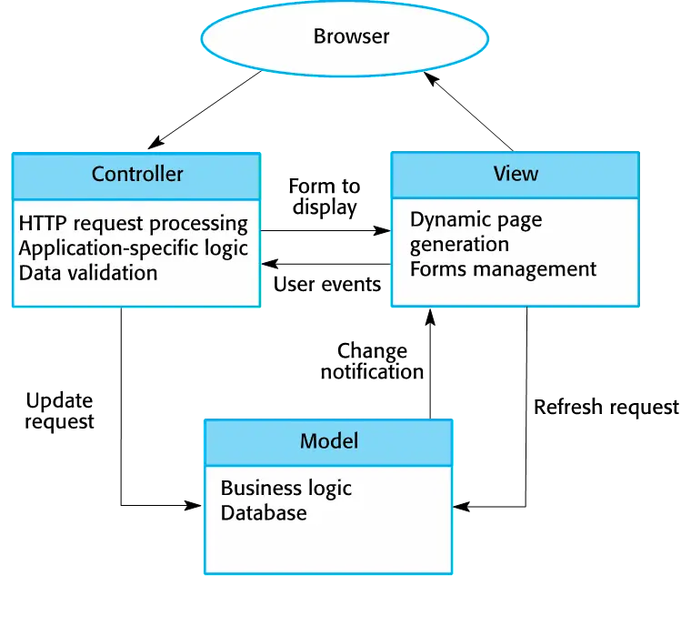
The Model-View-Controller (MVC) pattern
Separates presentation and interaction from the system data. The system is structured into three logical components that interact with each other. The Model component manages the system data and associated operations on that data. The View component defines and manages how the data is presented to the user. The Controller component manages user interaction (e.g., key presses, mouse clicks, etc.) and passes these interactions to the View and the Model.
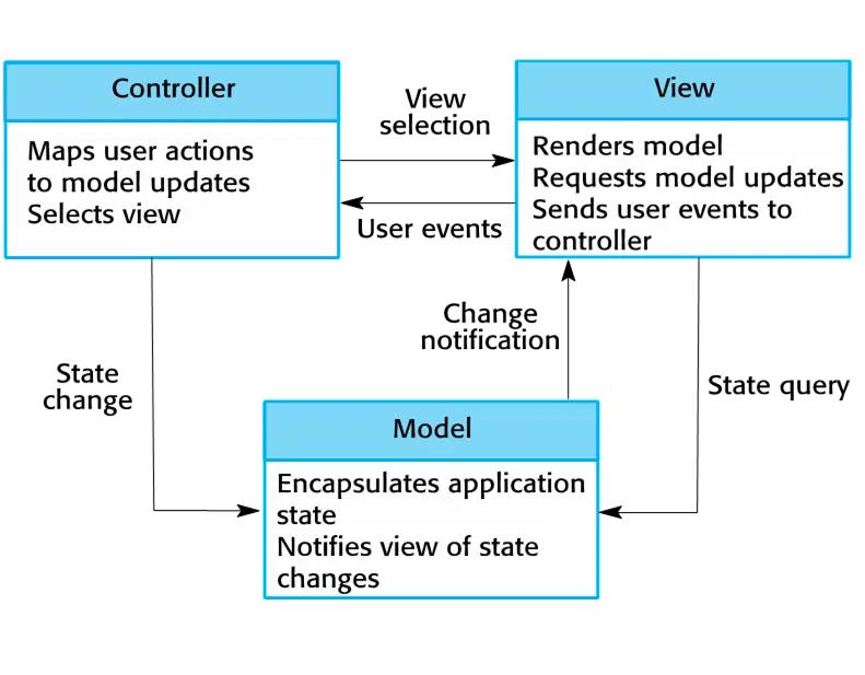
When used:
Used when there are multiple ways to view and interact with data. Also used when the future requirements for interaction and presentation of data are unknown.
Advantage:
Allows the data to change independently of its representation and vice versa. Supports presentation of the same data in different ways with changes made in one representation shown in all of them.
Disadventage:
Can involve additional code and code complexity when the data model and interactions are simple
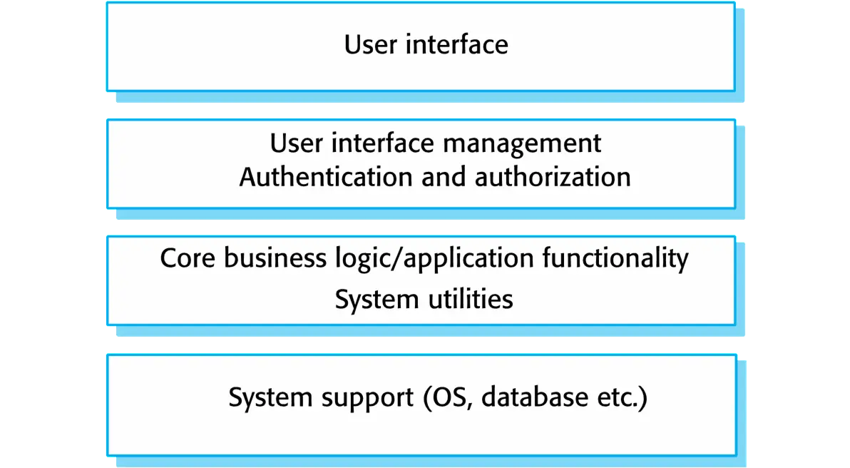
Layered architecture
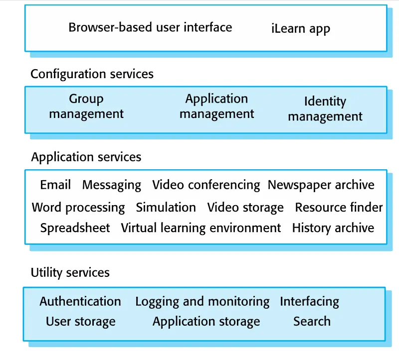
Organizes the system into layers with related functionality associated with each layer. A layer provides services to the layer above it so the lowest-level layers represent core services that are likely to be used throughout the system.
- Used to model the interfacing of sub-systems.
- Organises the system into a set of layers (or abstract machines) each of which provide a set of services.
- Supports the incremental development of sub-systems in different layers. When a layer interface changes, only the adjacent layer is affected.
- However, often artificial to structure systems in this way.
When used:
Used when building new facilities on top of existing systems; when the development is spread across several teams with each team responsibility for a layer of functionality; when there is a requirement for multi-level security
Advantage:
Allows replacement of entire layers so long as the interface is maintained. Redundant facilities (e.g., authentication) can be provided in each layer to increase the dependability of the system.
Disadvantage:
In practice, providing a clean separation between layers is often difficult and a high-level layer may have to interact directly with lower-level layers rather than through the layer immediately below it. Performance can be a problem because of multiple levels of interpretation of a service request as it is processed at each layer.
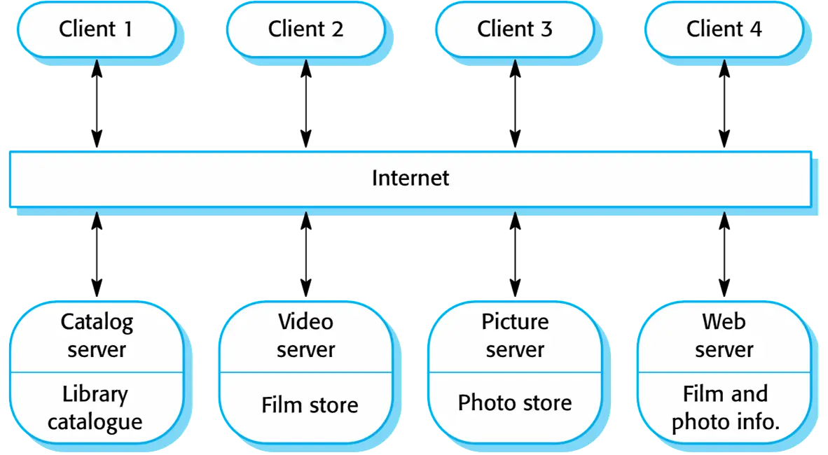
Client-server architecture
component:
- Client
- Servers
- Network
- Distributed system model which shows how data and
processing is distributed across a range of
components.
- Can be implemented on a single computer.
- Set of stand-alone servers which provide specific services such as printing, data management, etc.
- Set of clients which call on these services.
- Network which allows clients to access servers.
Communication:
- State less: just connect once
- State full: save previous data
Description
In a client–server architecture, the functionality of the system is organized into services, with each service delivered from a separate server. Clients are users of these services and access servers to make use of them.
When Used:
- Used when data in a shared database has to be accessed from a range of locations. Because servers can be replicated, may also be used when the load on a system is variable.
Adventages:
- The principal advantage of this model is that servers can be distributed across a network. General functionality (e.g., a printing service) can be available to all clients and does not need to be implemented by all services.
Disadvantages:
- Each service is a single point of failure so susceptible to denial of service attacks or server failure. Performance may be unpredictable because it depends on the network as well as the system. May be management problems if servers are owned by different organizations.
Pipe and filter architecture
- Functional transformations process their inputs to produce outputs.
- May be referred to as a pipe and filter model (as in UNIX shell).
- Variants of this approach are very common. When transformations are sequential, this is a batch sequential model which is extensively used in data processing systems.
- Not really suitable for interactive systems.
Description
The processing of the data in a system is organized so that each processing component (filter) is discrete and carries out one type of data transformation. The data flows (as in a pipe) from one component to another for processing.
When Used:
- Commonly used in data processing applications (both batch- and transaction-based) where inputs are processed in separate stages to generate related outputs.
Advantage:
Easy to understand and supports transformation reuse. Workflow style matches the structure of many business processes. Evolution by adding transformations is straightforward. Can be implemented as either a sequential or concurrent system.
Disadvantage:
The format for data transfer has to be agreed upon between communicating transformations. Each transformation must parse its input and unparsed its output to the agreed form. This increases system overhead and may mean that it is impossible to reuse functional transformations that use incompatible data structures
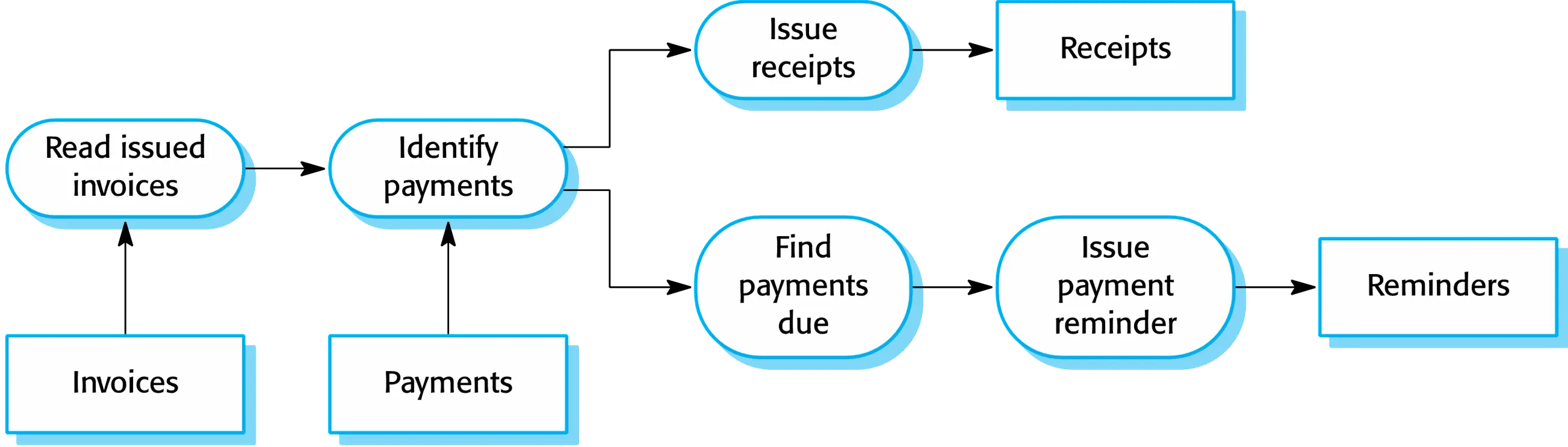
application architecture
- Application systems are designed to meet an organizational need.
- As businesses have much in common, their application systems also tend to have a common architecture that reflects the application requirements.
- A generic application architecture is an architecture for a type of software system that may be configured and adapted to create a system that meets specific requirements.
Use of application architectures
- As a starting point for architectural design.
- As a design checklist.
- As a way of organising the work of the development team.
- As a means of assessing components for reuse.
- As a vocabulary for talking about application types
Examples of application types
- Data processing applications
- Data driven applications that process data in batches without explicit user intervention during the processing.
- Transaction processing applications
- Process user requests for information from a database or requests to update the database.
- Data-centred applications that process user requests and update
information in a system database.
bank and e-commerce
- Event processing systems
- Applications where system actions depend on interpreting events from the system’s environment.
- Language processing systems
- Applications where the users’ intentions are specified in a formal
language that is processed and interpreted by the system.
Compilers; Command interpreters.
- Applications where the users’ intentions are specified in a formal
language that is processed and interpreted by the system.
Information systems architecture
- Information systems have a generic architecture that can be organized as a layered architecture.
- These are transaction-based systems as interaction with these systems generally involves database transactions.
- Layers include:
- The user interface
- User communications
- Information retrieval
- System database
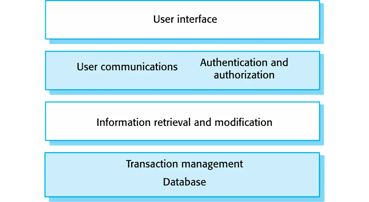
Web-based information systems
- Information and resource management systems are now usually web-based systems where the user interfaces are implemented using a web browser.
- For example, e-commerce systems are Internet-based resource management systems that accept electronic orders for goods or services and then arrange delivery of these goods or services to the customer.
- In an e-commerce system, the application-specific layer includes additional functionality supporting a ‘shopping cart’ in which users can place a number of items in separate transactions, then pay for them all together in a single transaction.
Language processing systems
pip filter
- Accept a natural or artificial language as input
and generate some other representation of that language.
data filter - May include an interpreter to act on the instructions in the language that is being processed.
- Used in situations where the easiest way to solve a
problem is to describe an algorithm or describe the system data
- Meta-case tools process tool descriptions, method rules, etc and generate tools.
Compiler components
- A lexical analyzer, which takes input language tokens and converts them to an internal form.
- A symbol table, which holds information about the names of entities (variables, class names, object names, etc.) used in the text that is being translated.
- A syntax analyzer, which checks the syntax of the language being translated.
- A syntax tree, which is an internal structure representing the program being compiled.
- A semantic analyzer that uses information from the syntax tree and the symbol table to check the semantic correctness of the input language text.
- A code generator that ‘walks’ the syntax tree and generates abstract machine code.
Key points
- A software architecture is a description of how a software system is organized.
- Architectural design decisions include decisions on the type of application, the distribution of the system, the architectural styles to be used.
- Architectures may be documented from several different perspectives or views such as a conceptual view, a logical view, a process view, and a development view.
- Architectural patterns are a means of reusing knowledge about generic system architectures. They describe the architecture, explain when it may be used and describe its advantages and disadvantages.
- Models of application systems architectures help us understand and compare applications, validate application system designs and assess large-scale components for reuse.
- Transaction processing systems are interactive systems that allow information in a database to be remotely accessed and modified by a number of users.
- Language processing systems are used to translate texts from one language into another and to carry out the instructions specified in the input language. They include a translator and an abstract machine that executes the generated language.
Design and implementation
Design and implementation
- Software design and implementation is the stage in the software engineering process at which an executable software system is developed.
- Software design and implementation activities are invariably
inter-leaved.
- Software design is a creative activity in which you identify software components and their relationships, based on a customer’s requirements.
- Implementation is the process of realizing the design as a program.
Build or buy
- In a wide range of domains, it is now possible to buy
off-the-shelf systems (COTS) that can be adapted and
tailored to the users’ requirements.
- For example, if you want to implement a medical records system, you can buy a package that is already used in hospitals. It can be cheaper and faster to use this approach rather than developing a system in a conventional programming language.
- When you develop an application in this way, the design process becomes concerned with how to use the configuration features of that system to deliver the system requirements.
Object-oriented design using the UML
- Structured object-oriented design processes involve developing a number of different system models.
- They require a lot of effort for development and maintenance of these models and, for small systems, this may not be cost-effective.
- However, for large systems developed by different groups design models are an important communication mechanism.
Process stages
- There are a variety of different object-oriented design processes that depend on the organization using the process.
- Common activities in these processes include:
- Define the context and modes of use of the system;
- Design the system architecture;
- Identify the principal system objects;
- Develop design models;
- Specify object interfaces.
System context and interactions
- Understanding the relationships between the software that is being designed and its external environment is essential for deciding how to provide the required system functionality and how to structure the system to communicate with its environment.
- Understanding of the context also lets you establish the boundaries of the system. Setting the system boundaries helps you decide what features are implemented in the system being designed and what features are in other associated systems.
Context and interaction models
- A system context model is a structural model that demonstrates the other systems in the environment of the system being developed.
- An interaction model is a dynamic model that shows how the system interacts with its environment as it is used.
Architectural design
- Once interactions between the system and its environment have been understood, you use this information for designing the system architecture.
- You identify the major components that make up the system and their interactions, and then may organize the components using an architectural pattern such as a layered or client-server model.
- The weather station is composed of independent subsystems that communicate by broadcasting messages on a common infrastructure.
Approaches to identificate Object class
- Use a grammatical approach based on a natural language description of the system.
- Base the identification on tangible things in the application domain.
- Use a behavioural approach and identify objects based on what participates in what behaviour.
- Use a scenario-based analysis. The objects, attributes and methods in each scenario are identified.
Design models
- Design models show the objects and object classes and relationships between these entities.
- There are two kinds of design model:
- Structural models describe the static structure of the system in terms of object classes and relationships.
- Dynamic models describe the dynamic interactions between objects.
Examples of design models
- Subsystem models that show logical groupings of
objects into coherent subsystems.
packages diagram - Sequence models that show the sequence of object interactions.
- State machine models that show how individual objects change their state in response to events.
- Other models include use-case models, aggregation models(聚合模型), generalisation models(概括模型), etc.
Design patterns
- Design patterns capture the best practices of experienced object-oriented software developers.
- Design patterns are solutions to general software development problems.
Benefits
- Speed up the development process by providing well tested, proven development/design paradigm
- Common Language with the other programmers
- Code Reusability
- Highly Maintainability
- Loosely coupled application(各个组件之间关联性较弱)
Pattern Elements
- Name:
- Provides a common vocabulary for software designers
- Higher level abstraction for the design
- Problem:
- What particular design issue or problem does the pattern address?
- What is the rationale and intent
- Solution:
- The basic elements providing the solution to the problem in terms of:structure,participants,collaborations
- Does not describe a particular concrete implementation
- Abstract description
- Concsequences:
- What are the results and trade-offs by applying the pattern:space and time trade-off,impact on system's flexibility,extensibility or portability
Types of Design Patterns
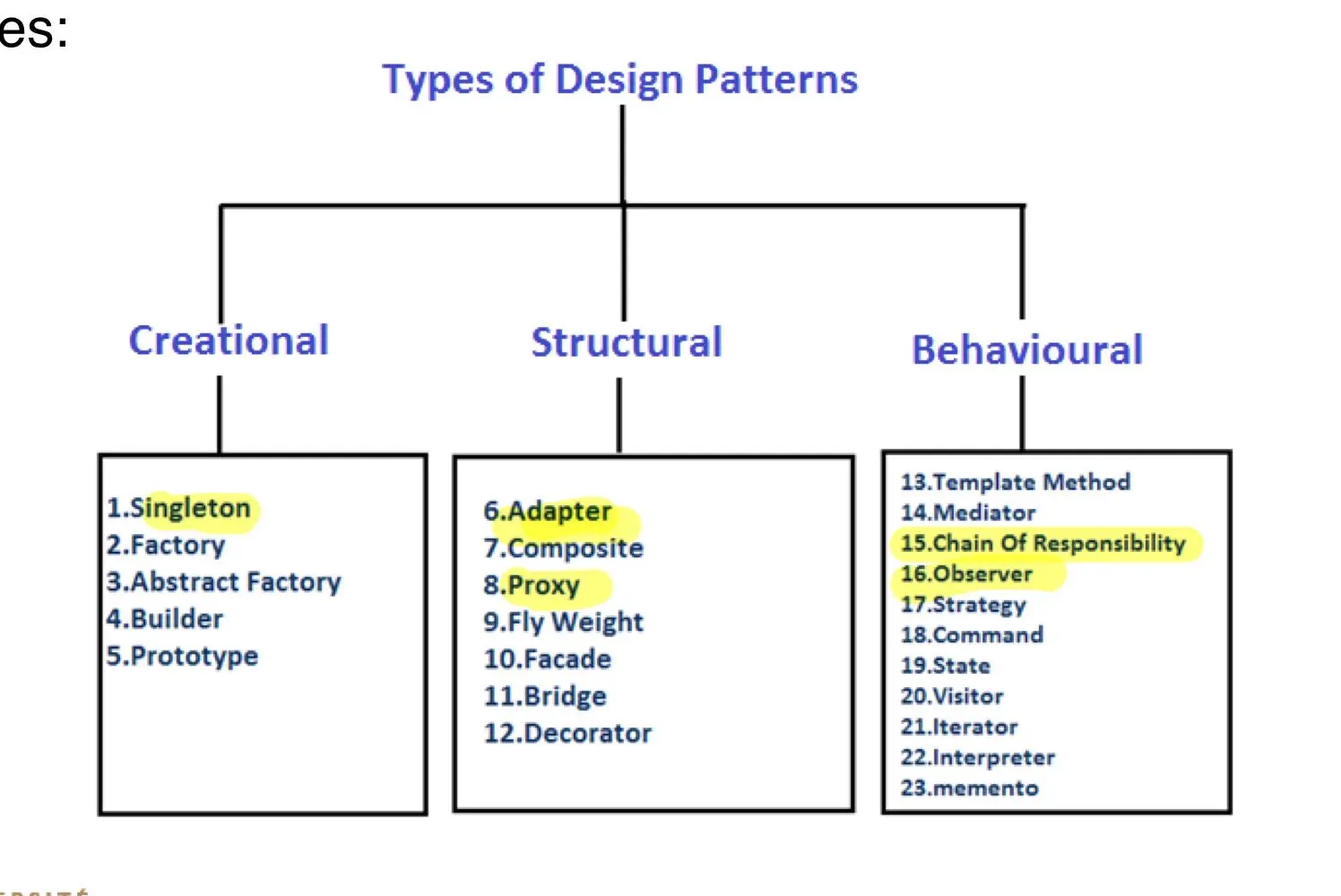
Creational Patterns
- The creational patterns deal with the best way to create instances of objects.
- In many cases, the exact nature or created object could vary with the needs of the program
- Abstracting the creation process into a special creator class can make your program more flexible and general
Singleton
- Ensures that a class has only one instance, and provides a global point of access to it
- Provide a global point of access to the object.
- Allow multiple instances in the future without affecting a singleton class' clients.
Example: 1
2
3
4
5
6
7
8
9
10
11
12
13
14
15
16
17
18
19
20
21
22
23
24
25
26
27
28
29
30
31
32
33
34
35
36
37
38
39
40class SingletonMeta(type):
"""
The Singleton class can be implemented in different ways in Python. Some
possible methods include: base class, decorator, metaclass. We will use the
metaclass because it is best suited for this purpose.
"""
_instances = {}
def __call__(cls, *args, **kwargs):
"""
Possible changes to the value of the `__init__` argument do not affect
the returned instance.
"""
if cls not in cls._instances:
instance = super().__call__(*args, **kwargs)
cls._instances[cls] = instance
return cls._instances[cls]
class Singleton(metaclass=SingletonMeta):
def some_business_logic(self):
"""
Finally, any singleton should define some business logic, which can be
executed on its instance.
"""
# ...
if __name__ == "__main__":
# The client code.
s1 = Singleton()
s2 = Singleton()
if id(s1) == id(s2):
print("Singleton works, both variables contain the same instance.")
else:
print("Singleton failed, variables contain different instances.")
Summary:
- The Singleton pattern ensures a class has only one instance, and provides a global point of access to it
- The class itself is responsible for keeping track of its sole instance
- The class can ensure that no other instance can be
created
- The class can provide a way to access the instance
Applicability
Use the Singleton pattern when a class in your program should have just a single instance available to all clients; for example, a single database object shared by different parts of the program.
- The Singleton pattern disables all other means of creating objects of a class except for the special creation method. This method either creates a new object or returns an existing one if it has already been created.
Use the Singleton pattern when you need stricter control over global variables.
- Unlike global variables, the Singleton pattern guarantees that there’s just one instance of a class. Nothing, except for the Singleton class itself, can replace the cached instance.
Note that you can always adjust this limitation and allow creating any number of Singleton instances. The only piece of code that needs changing is the body of the getInstance method.
Structural Pattern
Adapter
Structure
- The classes/objects participating in adapter pattern:
- Target - defines the domain-specific interface that Client uses.
- Adapter - adapts the interface Adaptee to the Target interface.
- Adaptee - defines an existing interface that needs adapting.
- Client - collaborates with objects conforming to the Target interface.
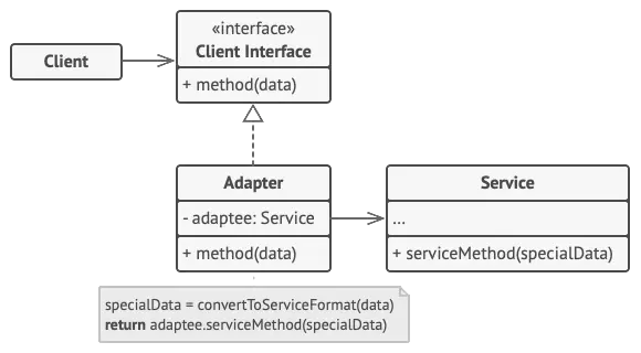
When to use Adapter
- When you have a class (Target) that invokes methods defined in an interface and you have another class (Adaptee) that doesn't implement the interface but implements the operations that should be invoked from the first class through the interface.
- You can change none of the existing code.
- You need an adapter to implement the interface that will be the bridge between the two classes.
1 | // Say you have two classes with compatible interfaces: |
Applicability
Use the Adapter class when you want to use some existing class, but its interface isn’t compatible with the rest of your code.
- The Adapter pattern lets you create a middle-layer class that serves as a translator between your code and a legacy class, a 3rd-party class or any other class with a weird interface.
Use the pattern when you want to reuse several existing subclasses that lack some common functionality that can’t be added to the superclass.
- You could extend each subclass and put the missing functionality into new child classes. However, you’ll need to duplicate the code across all of these new classes, which smells really bad.
The much more elegant solution would be to put the missing functionality into an adapter class. Then you would wrap objects with missing features inside the adapter, gaining needed features dynamically. For this to work, the target classes must have a common interface, and the adapter’s field should follow that interface. This approach looks very similar to the Decorator pattern.
Proxy
- It is a structural design pattern that lets you provide a substitute or placeholder for another object
Solution
- Create a proxy object that implements the same interface as the real object
- The proxy object(usually) contains a reference to real object
- Clients are given a reference to the proxy not the real object
- All client operations on the objects pass through the Proxy, allowing the Proxy to perform additional processing
- Proxies are useful wherever there is a need for a more sophisticated reference to an object than a simple pointer or simple reference can provide.
Example 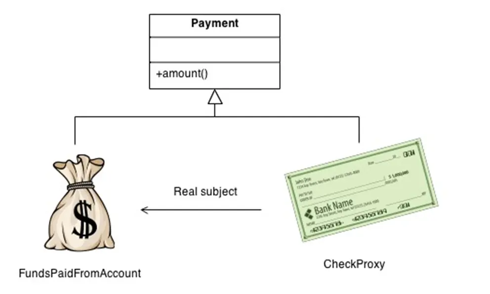
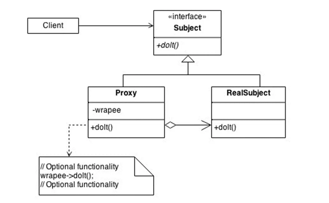
1 | // The interface of a remote service. |
Applicability
Lazy initialization (virtual proxy). This is when you have a heavyweight service object that wastes system resources by being always up, even though you only need it from time to time.
- Instead of creating the object when the app launches, you can delay the object’s initialization to a time when it’s really needed.
Access control (protection proxy). This is when you want only specific clients to be able to use the service object; for instance, when your objects are crucial parts of an operating system and clients are various launched applications (including malicious ones).
- The proxy can pass the request to the service object only if the client’s credentials match some criteria.
Local execution of a remote service (remote proxy). This is when the service object is located on a remote server.
- In this case, the proxy passes the client request over the network, handling all of the nasty details of working with the network.
Logging requests (logging proxy). This is when you want to keep a history of requests to the service object.
- The proxy can log each request before passing it to the service.
Caching request results (caching proxy). This is when you need to cache results of client requests and manage the life cycle of this cache, especially if results are quite large.
- The proxy can implement caching for recurring requests that always yield the same results. The proxy may use the parameters of requests as the cache keys.
Smart reference. This is when you need to be able to dismiss a heavyweight object once there are no clients that use it.
- The proxy can keep track of clients that obtained a reference to the service object or its results. From time to time, the proxy may go over the clients and check whether they are still active. If the client list gets empty, the proxy might dismiss the service object and free the underlying system resources.
The proxy can also track whether the client had modified the service object. Then the unchanged objects may be reused by other clients.
Behavioral Pattern
Chain of Responsibility
Avoid coupling sender of request to its receiver by giving more than one object chance to handle request. Chain receiving objects and pass request along until an object handles it.
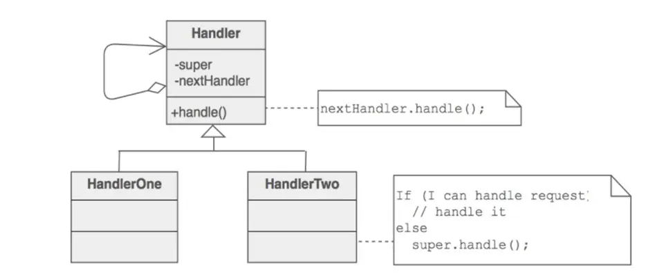
Handler – defines interface for handling requests. Can also implement successor link
ConcreteHandler – handles requests it is responsible for; otherwise forwards requests to successor.
Client – initiates request to a ConcreteHandler in the chain.
When to use
- More than 1 object may handle a request, and handle isn’t known beforehand.
- Want to issue request to one of several objects without specifying receiver explicitly.
- Set of objects that can handle a request should be specified dynamically
Benefits
- Decoupling of senders and receivers
- Added flexibility
- Sender doesn’t need to know specifically who the handlers are
Potential Drawbacks
- Client can’t explicitly specify who handles a request
- No guarantee of request being handled (request falls off end of chain)
Example
1 |
|
Applicability
Use the Chain of Responsibility pattern when your program is expected to process different kinds of requests in various ways, but the exact types of requests and their sequences are unknown beforehand.
- The pattern lets you link several handlers into one chain and, upon receiving a request, “ask” each handler whether it can process it. This way all handlers get a chance to process the request.
Use the pattern when it’s essential to execute several handlers in a particular order.
- Since you can link the handlers in the chain in any order, all requests will get through the chain exactly as you planned.
Use the CoR pattern when the set of handlers and their order are supposed to change at runtime.
- If you provide setters for a reference field inside the handler classes, you’ll be able to insert, remove or reorder handlers dynamically.
Observer
- Separates the display of the state of an object from the object itself and allows alternative displays to be provided.When the object state changes,all displays are automatically notified and updated to reflect the change.
Used when multiple displays of state are needed
Participants
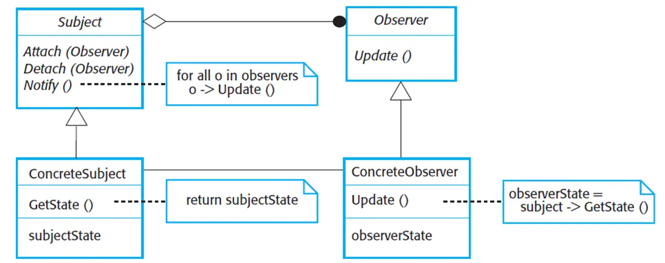
Subject - interface or abstract class defining the operations for attaching and de-attaching observers to the client. It is often referred to as “Observable”.
ConcreteSubject - concrete Subject class. It maintain the state of the observed object and when a change in its state occurs it notifies the attached Observers.
Observer - interface or abstract class defining the operations to be used to notify the registered Observer objects.
ConcreteObserver - concrete Observer subclasses that are attached to a particular Subject class. There may be different concrete observers attached to a single Subject that will provide a different view of that Subject.
Example
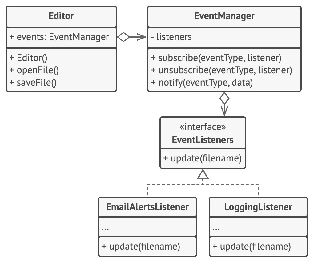
1 | // The base publisher class includes subscription management |
Class Example
Channel.java
1
2
3
4
5
public interface Channel {
    public void update(Object o);
}
NewsAgency.java
1 |
|
NewsAgencyTest.java 1
2
3
4
5
6
7
8
9
10
11
12
13
14
15
16
17
18
19
20
21
22
23
24
import static org.junit.Assert.assertEquals;
import org.junit.Test;
public class NewsAgencyTest {
public void whenChangingNewsAgencyState_thenNewsChannelNotified() {
NewsAgency observable = new NewsAgency();
NewsChannel observer = new NewsChannel();
observable.addObserver(observer);
observable.setNews("news");
assertEquals(observer.getNews(), "news");
}
}
1 |
|
Applicability
Use the Observer pattern when changes to the state of one object may require changing other objects, and the actual set of objects is unknown beforehand or changes dynamically.
- You can often experience this problem when working with classes of the graphical user interface. For example, you created custom button classes, and you want to let the clients hook some custom code to your buttons so that it fires whenever a user presses a button.
The Observer pattern lets any object that implements the subscriber interface subscribe for event notifications in publisher objects. You can add the subscription mechanism to your buttons, letting the clients hook up their custom code via custom subscriber classes.
Use the pattern when some objects in your app must observe others, but only for a limited time or in specific cases.
- The subscription list is dynamic, so subscribers can join or leave the list whenever they need to.
Software Testing
Terms
- acceptance criteria:
- A set of conditions that must be met in order for a software system to be considered as meeting the requirements of users, customer or other authorized entity.
- acceptance testing:
- A test level that focuses on determining whether to accept the system.
- Includ Alpha testing and Beta testing.
- alpha testing : A type of acceptance testing performed in the developer's test environment by roles outside the development organization.
- beta testing: A type of acceptance testing performed at an external site to the developer's test environment by roles outside the development organization.
- accessibility testing:
- Testing to determine the ease by which users with disabilities can use a component or system.
- Audit :
- An independent examination of a work product, process, or set of processes that is performed by a third party to assess compliance with specifications, standards, contractual agreements, or other criteria.
- Avaliability:
- The degree to which a component or system is operational and accessible when required for use.
- compatibility(兼容性):
- The degree to which a component or system can exchange information with other components or systems, and/or perform its required functions while sharing the same hardware or software environment.
- compliance:
- Adherence of the component or system to standards, conventions or regulations in laws and similar prescriptions
- configuration:
- The composition of a component or system as defined by the number, nature, and interconnections of its constituent parts.
- configuration management tool:
- A tool that provides support for the identification and control of configuration items, their status over changes and versions, and the release of baselines consisting of configuration items.
- data flow:
- An abstract representation of the sequence and possible changes of the state of data objects, where the state of an object is any of creation, usage, or destruction.
- debugging:
- The process of finding, analyzing and removing the causes of failures in a component or system
- Effectiveness
- Extent to which correct and complete goals are achieved.
- efficiency:
- The degree to which resources are expended in relation to the accuracy and completeness with which a user achieves goals.
- Error Classification
- Anomaly: Any condition that deviates from expectation based on requirements specifications, design documents, user documents, standards, etc., or from someone's perception or experience. Anomalies may be found during, but not limited to, reviewing, testing, analysis, compilation, or use of software products or applicable documentation.
- defect: An imperfection or deficiency in a work product where it does not meet its requirements or specifications.
- error: A human action that produces an incorrect result.
- fail: A test is deemed to fail if its actual result does not match its expected result.
- failure: An event in which a component or system does not perform a required function within specified limits.
- failure rate: The ratio of the number of failures of a given category to a given unit of measure.
- bug: Result from coding errors, logical mistakes, or design flaws, leading to issues such as program crashes, incorrect output, or abnormal behavior.
- formal review
- A type of review that follows a defined process with a formally documented output.
- informal review
- A type of review that does not follow a defined process and has no formally documented output.
- inspection
- A type of formal review to identify issues in a work product, which provides measurement to improve the review process and the software development process.
- integrity
- The degree to which a component or system allows only authorized access and modification to a component, a system or data.
- interoperability
- The degree to which two or more components or systems can exchange information and use the information that has been exchanged.
- Load testing
- A type of performance testing conducted to evaluate the behavior of a component or system under varying loads, usually between anticipated conditions of low, typical, and peak usage.
- memory leak
- A memory access failure due to a defect in a program's dynamic store allocation logic that causes it to fail to release memory after it has finished using it.
Definition
Program testing
Testing is intended to show that a program does what it is intended to do and to discover program defects before it is put into use.
Can reveal the presence of errors NOT their absence. ### Goals
To demonstrate to the developer and the customer that the software meets its requirements.
- For custom software, this means that there should
be at least one test for every requirement in the
requirements document. For generic software products,
it means that there should be tests for all of the system
features, plus combinations of these features,
that will be incorporated in the product release.
To discover situations in which the behavior of the software is incorrect, undesirable or does not conform to its specification.
- Defect testing is concerned with rooting out undesirable system behavior such as system crashes, unwanted interactions with other systems, incorrect computations and data corruption.
Validation and defect testing
- The first goal leads to validation testing
- You expect the system to perform correctly using a given set of test cases that reflect the system’s expected use.
- Step
- To demonstrate to the developer and the system customer that the software meets its requirements
- A successful test shows that the system operates as intended
- The second goal leads to defect testing
- The test cases are designed to expose defects. The test cases in defect testing can be deliberately obscure and need not reflect how the system is normally used.
- Step
- To discover faults or defects in the software where its behavior is incorrect or not in conformance with its specification
- A successful test is a test that makes the system perform incorrectly and so exposes a defect in the system
Verification vs validation
- Verification: "Are we building the product right”.
- The software should conform to its specification.(design by software engineers)
- Validation: "Are we building the right product”.
- The software should do what the user really requires.
Inspections and testing
- Inspections and testing are complementary and not opposing verification techniques.
- Inspections can check conformance with a
specification but not conformance with the customer’s
real requirements. (
verification) - Inspections cannot check
non-functional characteristics such as performance,
usability, etc.
- Software inspections Concerned with analysis of the
static system representation to discover
problems (static verification)
- May be supplement by tool-based document and code analysis.
- Software testing Concerned with
exercising and observing product behaviour
(dynamic verification)
- The system is executed with test data and its operational behaviour is observed.
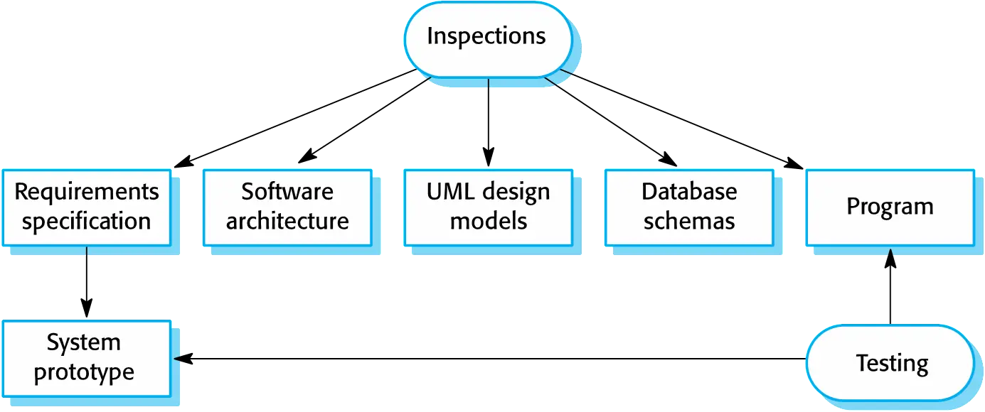
Inspectiong:
- These involve people examining the source representation with the aim of discovering anomalies and defects.
- Inspections not require execution of a system so may be used before implementation.
- They may be applied to any representation of the system (requirements, design,configuration data, test data, etc.).
- They have been shown to be an effective technique for discovering program errors.
Advantages:
- During testing, errors can mask (hide) other errors. Because inspection is a static process, you don’t have to be concerned with interactions between errors.
- Incomplete versions of a system can be inspected without additional costs. If a program is incomplete, then you need to develop specialized test harnesses to test the parts that are available.
- As well as searching for program defects, an inspection can also consider broader quality attributes of a program, such as compliance with standards, portability and maintainability.
Stages of testing
- Development testing, where the system is tested during development to discover bugs and defects.
- Release testing, where a separate testing team test a complete version of the system before it is released to users.
- User testing, where users or potential users of a system test the system in their own environment.
Development testing
- Development testing includes all testing activities that are carried
out by the team developing the system.
- Unit testing, where individual
program units or object classes are
tested. Unit testing should focus on testing the
functionality of objects or methods.
- Component testing, where several individual units are integrated to create composite components. Component testing should focus on testing component interfaces.
- System testing, where some or all of the components in a system are integrated and the system is tested as a whole. System testing should focus on testing component interactions
- Unit testing, where individual
program units or object classes are
tested. Unit testing should focus on testing the
functionality of objects or methods.
Unit testing
- Unit testing is the process of testing individual components in isolation.
- It is a defect testing process.
- Units may be:
- Individual functions or methods within an object
- Object classes with several attributes and methods
- Composite components with defined interfaces used to access their functionality.
Object class testing
- Complete test coverage of a class involves
- Testing all operations associated with an object
- Setting and interrogating all object attributes
- Exercising the object in all possible states.
- Inheritance makes it more difficult to design object class tests as the information to be tested is not localised.
Automated test components
- A setup part, where you initialize the system with the test case, namely the inputs and expected outputs.
- A call part, where you call the object or method to be tested.
- An assertion part where you compare the result of the call with the expected result. If the assertion evaluates to true, the test has been successful if false, then it has failed.
2 types of unit test
- The first of these should reflect normal operation of a program and should show that the component works as expected.
- The other kind of test case should be based on testing experience of where common problems arise. It should use abnormal inputs to check that these are properly processed and do not crash the component.
Testing strategies
- Partition testing, where you identify groups of
inputs that have common characteristics and should be processed in the
same way.
- You should choose tests from within each of these groups.
- Input data and output results often fall into different classes where all members of a class are related.
- Each of these classes is an equivalence partition or domain where the program behaves in an equivalent way for each class member.
- Test cases should be chosen from each partition
- Guideline-based testing, where you use testing guidelines to choose test cases. These guidelines reflect previous experience of the kinds of errors that programmers often make when developing components.
General testing guidelines
- Choose inputs that force the system to generate all error messages
- Design inputs that cause input buffers to overflow (like size of file or length of string)
- Repeat the same input or series of inputs numerous times
- Force invalid outputs to be generated
- Force computation results to be too large or too small.
Component testing
- Software components are often composite components that are made up
of several interacting objects.
- For example, in the weather station system, the reconfiguration component includes objects that deal with each aspect of the reconfiguration.
- You access the functionality of these objects through the defined component interface.
- Testing composite components should therefore focus on showing that
the component interface behaves according to its specification.
- You can assume that unit tests on the individual objects within the component have been completed.
Interface testing
- Objectives are to detect faults due to interface errors or invalid assumptions about interfaces.
- Interface types
- Parameter interfaces: Data passed from one method or procedure to another.
- Shared memory interfaces: Block of memory is shared between procedures or functions.
- Procedural interfaces: Sub-system encapsulates a set of procedures to be called by other sub-systems.
- Message passing interfaces: Sub-systems request services from other sub-systems
Interface errors
- Interface misuse
- A calling component calls another component and makes an error in its use of its interface e.g. parameters in the wrong order.
- Interface misunderstanding
- A calling component embeds assumptions about the behaviour of the called component which are incorrect.
- Timing errors
- The called and the calling component operate at different speeds and out-of-date information is accessed.
Interface testing guidelines
- Design tests so that parameters to a called procedure are at the extreme ends of their ranges.
- Always test pointer parameters with null pointers.
- Design tests which cause the component to fail.
- Use stress testing in message passing systems.
- In shared memory systems, vary the order in which components are activated.
System testing
- System testing during development involves integrating components to create a version of the system and then testing the integrated system.
- The focus in system testing is testing the interactions between components.
- System testing checks that components are compatible, interact correctly and transfer the right data at the right time across their interfaces.
- System testing tests the emergent behavior of a system.
System and component testing
- During system testing, reusable components that have been separately developed and off-the-shelf systems may be integrated with newly developed components. The complete system is then tested.
- Components developed by different team members or
sub-teams may be integrated at this stage. System testing is a
collective rather than an individual process.
- In some companies, system testing may involve a separate testing team with no involvement from designers and programmers.
Use-case testing
- The use-cases developed to identify system interactions can be used as a basis for system testing.
- Each use case usually involves several system components so testing the use case forces these interactions to occur.
- The sequence diagrams associated with the use case documents the components and interactions that are being tested.
Test cases derived from sequence diagram
- An input of a request for a report should have an associated
acknowledgement. A report should ultimately be returned from the
request.
- You should create summarized data that can be used to check that the report is correctly organized.
- An input request for a report to WeatherStation results in a
summarized report being generated.
- Can be tested by creating raw data corresponding to the summary that you have prepared for the test of SatComms and checking that the WeatherStation object correctly produces this summary. This raw data is also used to test the WeatherData object.
Testing policies
- Exhaustive system testing is impossible so testing policies which define the required system test coverage may be developed.
- Examples of testing policies:
- All system functions that are accessed through menus should be tested.
- Combinations of functions (e.g. text formatting) that are accessed through the same menu must be tested.
- Where user input is provided, all functions must be tested with both correct and incorrect input.
Test-driven development
- Test-driven development (TDD) is an approach to program development in which you inter-leave testing and code development.
- Tests are written before code and ‘passing’ the tests is the critical driver of development.
- You develop code incrementally, along with a test for that increment. You don’t move on to the next increment until the code that you have developed passes its test.
- TDD was introduced as part of agile methods such as Extreme Programming. However, it can also be used in plan-driven development processes.
TDD process activities
- Start by identifying the increment of functionality that is required. This should normally be small and implementable in a few lines of code.
- Write a test for this functionality and implement this as an automated test.
- Run the test, along with all other tests that have been implemented. Initially, you have not implemented the functionality so the new test will fail.
- Implement the functionality and re-run the test.
- Once all tests run successfully, you move on to implementing the next chunk of functionality.
Benefits
- Code coverage
- Every code segment that you write has at least one associated test so all code written has at least one test.
- Regression testing
回归测试- A regression test suite is developed incrementally as a program is developed.
- check that changes have not ‘broken’ previously working code.
- always automated testing
- All tests are rerun every time a change is made to the program.
- Tests must run ‘successfully’ before the change is committed
- Simplified debugging
- When a test fails, it should be obvious where the problem lies. The newly written code needs to be checked and modified.
- System documentation
- The tests themselves are a form of documentation that describe what the code should be doing.
Release testing
- Release testing is the process of testing a particular release of a system that is intended for use outside of the development team.
- The primary goal of the release testing process is to convince the
supplier of the system that it is good enough for use.
- Release testing, therefore, has to show that the system delivers its specified functionality, performance and dependability, and that it does not fail during normal use.
- Release testing is usually a black-box testing process where tests are only derived from the system specification.
Release testing and system testing
- Release testing is a form of system testing.
- Important differences:
- A separate team that has not been involved in the system development, should be responsible for release testing.
- System testing by the development team should focus on discovering bugs in the system (defect testing). The objective of release testing is to check that the system meets its requirements and is good enough for external use (validation testing).
Requirements based testing (validation)
- Requirements-based testing involves examining each requirement and developing a test or tests for it.
- Mentcare system requirements:
- If a patient is known to be allergic to any particular medication, then prescription of that medication shall result in a warning message being issued to the system user.
- If a prescriber chooses to ignore an allergy warning, they shall provide a reason why this has been ignored.
Software Evolution
Software change
- Software change is inevitable
- New requirements emerge when the software is used;
- The business environment changes;
- Errors must be repaired;
- New computers and equipment is added to the system;
- The performance or reliability of the system may have to be improved.
- A key problem for all organizations is implementing and managing change to their existing software systems.
Importance
- Organizations have huge investments in their software systems - they are critical business assets.
- To maintain the value of these assets to the business, they must be changed and updated.
- The majority of the software budget in large companies is devoted to changing and evolving existing software rather than developing new software.
Evolution and servicing
- Evolution
- The stage in a software system’s life cycle where it is in operational use and is evolving as new requirements are proposed and implemented in the system.
- Servicing
- At this stage, the software remains useful but the only changes made are those required to keep it operational i.e. bug fixes and changes to reflect changes in the software’s environment. No new functionality is added.
- Phase-out
win 7,win xp- The software may still be used but no further changes are made to it.
Evolution processes
- Software evolution processes depend on
- The type of software being maintained;
- The development processes used;
- The skills and experience of the people involved.
- Proposals for change are the driver for system
evolution.
- Should be linked with components that are affected by the change, thus allowing the cost and impact of the change to be estimated.
- Change identification and evolution continues throughout the system lifetime.
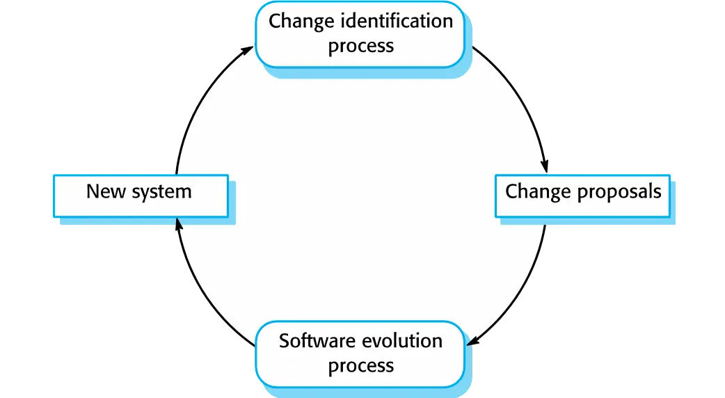
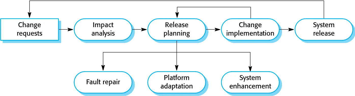
Change implementation
- Iteration of the development process where the revisions to the system are designed, implemented and tested.
- A critical difference is that the first stage of change implementation may involve program understanding, especially if the original system developers are not responsible for the change implementation.
- During the program understanding phase, you have to understand how the program is structured, how it delivers functionality and how the proposed change might affect the program.
Urgent change requests
- Urgent changes may have to be implemented without
going through all stages of the software
engineering process
- If a serious system fault has to be repaired to allow normal operation to continue;
- If changes to the system’s environment (e.g. an OS upgrade) have unexpected effects;
- If there are business changes that require a
very rapid response (e.g. the release of a competing
product).
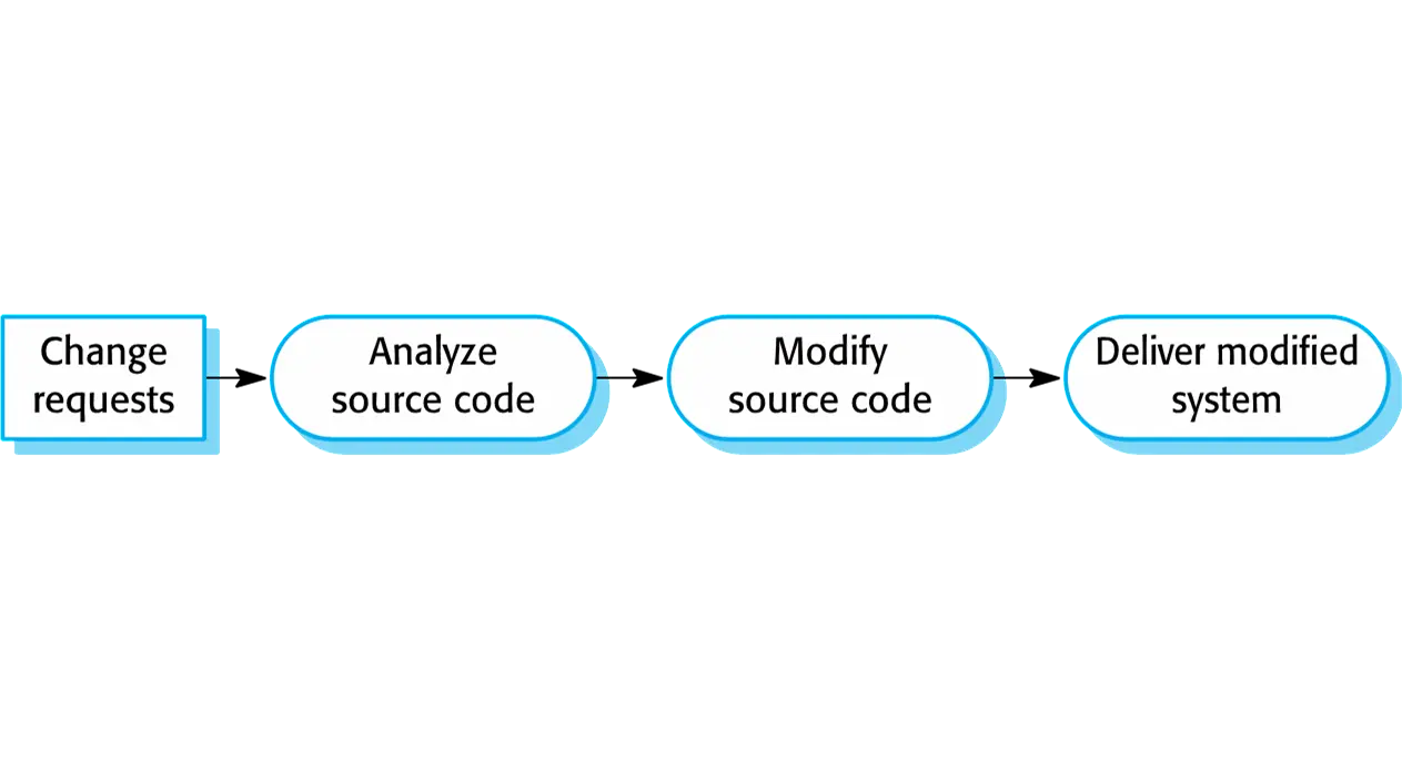
Agile methods and evolution
- Agile methods are based on incremental development
so the transition from development to evolution is a
seamless one.
- Evolution is simply a continuation of the development process based on frequent system releases.
- Automated regression testing is particularly valuable when changes are made to a system.
- Changes may be expressed as additional user stories.
Handover problems
- Where the development team have used an agile
approach, but the evolution team is
unfamiliar with agile methods and prefer a
plan-based approach.
- The evolution team may expect detailed documentation to support evolution, and this is not produced in agile processes.
- Where a plan-based approach has been used for
development, but the evolution team
prefer to use agile methods.
- The evolution team may have to start from scratch developing automated tests and the code in the system may not have been refactored and simplified as is expected in agile development.
 wechat
 alipay